
230 V 50Hz AC (or 110V 60Hz) Main Operated LED Powerful NIGHT LAMPCircuit
 Main Operated LED Powerful NIGHT LAMPCircuit")
For the implementation of a circuit designed to operate at 110V 60Hz, it is essential to make specific adjustments to the components to ensure safe and effective operation. The circuit typically utilizes a capacitor (C1) that should be replaced with a 0.68 µF polyester capacitor rated for at least 250 volts. This change is crucial as it allows the circuit to handle the lower frequency and higher current associated with the 110V supply.
In addition to the capacitor modification, the resistor R1 must be adjusted to a value of 220 ohms with a power rating of 1/2 watt. This adjustment is necessary to maintain the appropriate current flow through the circuit, which is critical for the operation of the LEDs. The specified LEDs should be bright, operating at 3.2 volts and drawing 25mA, ensuring adequate brightness and visibility in the intended application.
The first circuit diagram provided serves as the primary reference for the correct configuration of these components. The second diagram, while included for experimental purposes, may not provide reliable results and should not be constructed in a typical home environment. Safety precautions must always be observed when working with electrical circuits, particularly when dealing with high voltage supplies. Proper insulation, component ratings, and adherence to electrical standards are vital to prevent any hazards or malfunctions.If you have plane to use this Circuit on 110V 60Hz instead of 230V, 50Hz, or want to modify this circuit, Then See the Section " Common Question about this Circuit" below the "instruction". Also Note that here is two circuit diagrams, so the first one is recommended. the second one (as i tried) is for experimental purpose only, so don`t trythe second one at home. i will be not liable for any Damage/Loss(es). Please be careful because your safety is better than everything. If Your plane is to use this circuit with 110V 60Hz AC main Supply then change CI to 0. 68 F (684 / 250Volts) polyester capacitor. Reduce the value of R1 to 220 © 1/2 watt. Ensure that you use 3. 2 volt 25mA Bright LED`s 🔗 External reference
Related Circuits
This compact design forms a remotely operated switch that receives its control signal via the mains voltage. The switch is operated using the mains remote transmitter described elsewhere in this issue. With this transmitter, a switch should be connected...
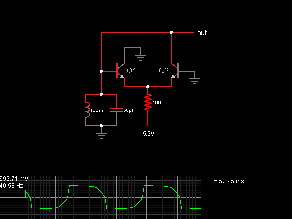
When the oscillator starts, Q2 is in a conducting state; the current flows from the capacitor, charging it until the voltage across it is sufficient to allow current to flow through the inductor. As the current through the inductor...
Have you ever imagined controlling your home appliances using your cell phone? Numerous circuits exist for this application, typically utilizing a telephone. This circuit has been modified and redesigned for compatibility with a standard cell phone headphone jack. To...
A request has been made to design a unique outdoor Christmas decoration in the form of an LED-illuminated star. The objective is to create a very bright display using 30 ultra-bright 8mm LEDs. The plan includes sanding the domes...
Supply voltage: 12 V. Supply current: 10 mA in stand-by, max. 80 mA. Input voltage: min. 20 mV rms. Indication range: 30 dB. LED currents: 7 mA. Ref. voltage of IC2: 5 V More: R1 - trimmer 100 k...
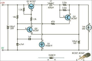
This circuit is designed to drive 1W LEDs that are commonly available. It addresses their non-linear voltage-to-current relationship and variations in forward voltage. The circuit utilizes a constant current driver configuration to ensure that the LEDs operate efficiently while maintaining...