
Mini Audio Amplifier Circuit Schematic Diagram BC547 Transistor
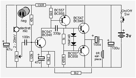
The Mini Audio Amplifier Circuit is designed to amplify low-level audio signals while maintaining low power consumption and compact size. The circuit typically incorporates a push-pull configuration using complementary transistors, which allows for efficient amplification of audio signals. This configuration helps to minimize distortion and improve linearity, ensuring high-quality audio output.
In this circuit, the input audio signal is fed into the base of the first transistor, which acts as a voltage amplifier. The output from this transistor is then fed into the second transistor, configured in a push-pull arrangement. This arrangement allows for both halves of the audio waveform to be amplified, providing a more complete and accurate representation of the original signal.
The power supply for this circuit is designed to operate at low voltage, typically around 5V, which contributes to the low power consumption of less than 3mA. This makes the circuit suitable for battery-powered applications where efficiency is critical. The output is typically connected to small speakers or headphones, making it ideal for portable audio devices.
Overall, the Mini Audio Amplifier Circuit is a practical solution for applications requiring audio amplification with minimal power usage and compact design, making it suitable for various consumer electronics.The following circuit shows about Mini Audio Amplifier Circuit Schematic Diagram. Features: power less than 3mA, small output, using push-pull .. 🔗 External reference
Related Circuits
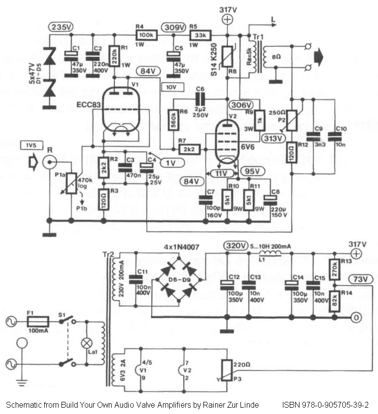
Direct-coupled single-ended (SE) 6V6 and 6V6GT tube amplifier schematic with ECC83 driver stage. From the book "Build Your Own Audio Valve Amplifier" by Rainer zur Linde. The described circuit represents a direct-coupled single-ended tube amplifier utilizing 6V6 or 6V6GT vacuum...

A simple 16-volt switching power supply circuit can be constructed using the provided diagram, which is based on the MAX668 constant-frequency, pulse-width modulating (PWM), current-mode DC-DC controller. This integrated circuit is designed for a wide range of DC-DC conversion...
One of the more frequently requested projects on HeadWize has been a switchbox for selecting multiple audio inputs. I built this passive preamp/switchbox several years ago to switch between two stereo sources (a portable FM tuner and portable CD...
This circuit generates audio musical notes that can be heard from a distance of up to 10 meters. It consists of two main components: an infrared (IR) music transmitter and an IR music receiver. The IR music transmitter operates...
Powered by a solar panel, the circuit provides a 5V pure regulated DC voltage. It consists of an oscillator transistor and a regulator transistor. The solar panel charges the battery when sunlight is sufficient to generate a voltage above...
The transmitter's function is to modulate the original signal frequency of the message-carrying signal, a process known as modulation. The circuit realization of this function is referred to as a frequency modulation (FM) circuit. FM tuners are categorized into...