
2.4 GHz Field Strength Meter Circuit with Optional Amplifier

A field strength meter circuit typically consists of several key components, including an antenna, a RF amplifier, a detector, and a display unit. The antenna captures the electromagnetic waves emitted by the radio transmitter, converting them into a small RF signal. This RF signal is then amplified by the RF amplifier to ensure it is strong enough for further processing.
After amplification, the signal is directed to a detector, which demodulates the RF signal to extract the envelope of the waveform, providing a representation of the field strength. The output from the detector is usually a DC voltage that corresponds to the strength of the received signal. This voltage is then fed to a display unit, which can be an analog meter or a digital readout, allowing the user to visually assess the strength of the radio field.
In some designs, additional features may be included, such as calibration controls, frequency selectivity filters, or even data logging capabilities. Calibration controls are essential for ensuring accurate measurements, allowing the user to adjust the meter to account for variations in the environment or the characteristics of the antenna. Frequency filters can help isolate specific frequency bands, providing more precise measurements for particular applications.
Overall, a field strength meter circuit is a vital component in the field of radio frequency engineering, aiding in the design, testing, and maintenance of radio transmission systems.Field strength meter is a must have equipment if you`re dealing with radio transmitter electronics. Here is one example of this kind of circuit that works for. 🔗 External reference
Related Circuits
This circuit was built to charge two series lithium cells (3.6 volts each, 1 Amp Hour capacity) installed in a portable transistor radio. The circuit is designed to efficiently charge two lithium-ion cells connected in series. Each cell has a...
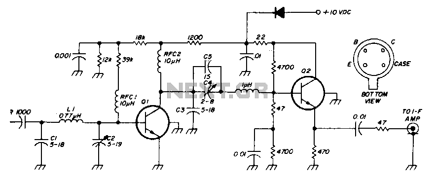
The low-noise preamplifier features a noise figure of 1 dB at 30 MHz and a 3 dB bandwidth of 10 MHz. The gain is 19 dB. The total current drain with a +10 volt supply is 13 mA. The...
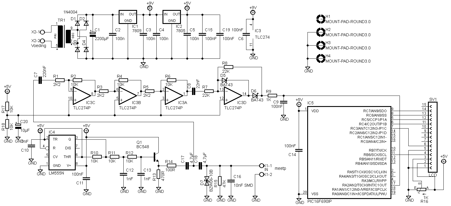
Two versions are provided. The first version is based on the original schematics, with the modification of replacing SMD capacitors with standard through-hole capacitors. The second version features some modifications, including the removal of the transformer and the addition...
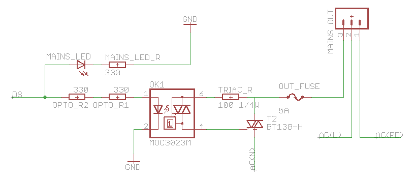
The heatsink on the triac is somewhat unclear. A maximum value of 10°C/W has been calculated, which raises concerns. The calculation is as follows: (maximum temperature - room temperature) / (maximum on-stage voltage * (milliamps / voltage) - junction-to-base...

This is a design circuit for a soft light dimmer. The circuit utilizes the IGBT STGP10N50A and the TS555 timer as the main components. The timer is triggered by the zero crossing voltage pulse. The time constant, determined by...
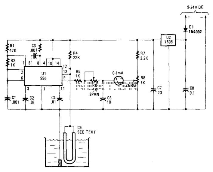
Using a capacitor sensor to detect water levels is a straightforward sensing method. This circuit employs C5, which consists of 10 to 20 inches of #22 enameled wire as one of the electrodes. The oscillator, an NE556 timer, experiences...