
Water-Level Measurement Circuit

The water level detection circuit operates on the principle of capacitance variation with changing water levels. The NE556 timer is configured in an astable mode, generating a square wave output whose frequency is influenced by the capacitance of the sensor, represented by C5. As the water level rises or falls, the dielectric constant around the wire electrode changes, thus altering the capacitance.
To implement this circuit, the 10 to 20 inches of #22 enameled wire is coiled or arranged in such a way that it can effectively sense the water level. This wire acts as one plate of a capacitor, with the water serving as the dielectric medium and the surrounding environment as the other plate.
The output frequency from the NE556 timer is monitored at pin 9, which can be connected to a frequency counter or a simple analog meter. The meter provides a visual indication of the water level based on the frequency shift. The frequency output can be calibrated to correspond to specific water levels, allowing for precise monitoring.
Adjusting the length or configuration of C5 can optimize the sensitivity and response time of the sensor, making it adaptable for various applications, such as in tanks, wells, or other water storage systems. Proper calibration and testing are essential to ensure accurate readings and reliable performance in the desired environment. Using a capacitor sensor to detect a water level is a simple method of sensing. This circuit uses C5, which is 10" to 20" of #22 enamelled wire as one electrode. This shifts the oscillator, an NE556 timer, in frequency. The frequency shift depends on the capacitance change, which in turn varies with water level. A meter connected to pin 9 of the 556 is used as an indicator. C5 can be made larger or smaller to suit the intended application.
Related Circuits
This circuit consists of a light measurement circuit and a flash circuit, as illustrated in the accompanying figure. It is applicable in the POPTICS (a popular integrated camera), the Franka X-500, and the WIZEN-860S cameras. The light measurement circuit...
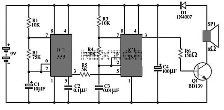
The circuit utilizes IC1 to create an astable multivibrator configuration. It is designed to generate a low-frequency output of approximately 1 Hz at pin 3, which is determined by the resistor values R1, R2 and capacitor C1. The output...
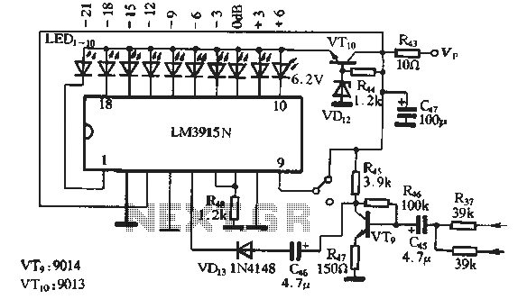
The circuit features a manual recording level control function. When in recording mode, the recording level is indicated by the LM3915N. The sound recording circuit, as illustrated in Figure 3-17, employs an RC network and an associated audio recording...
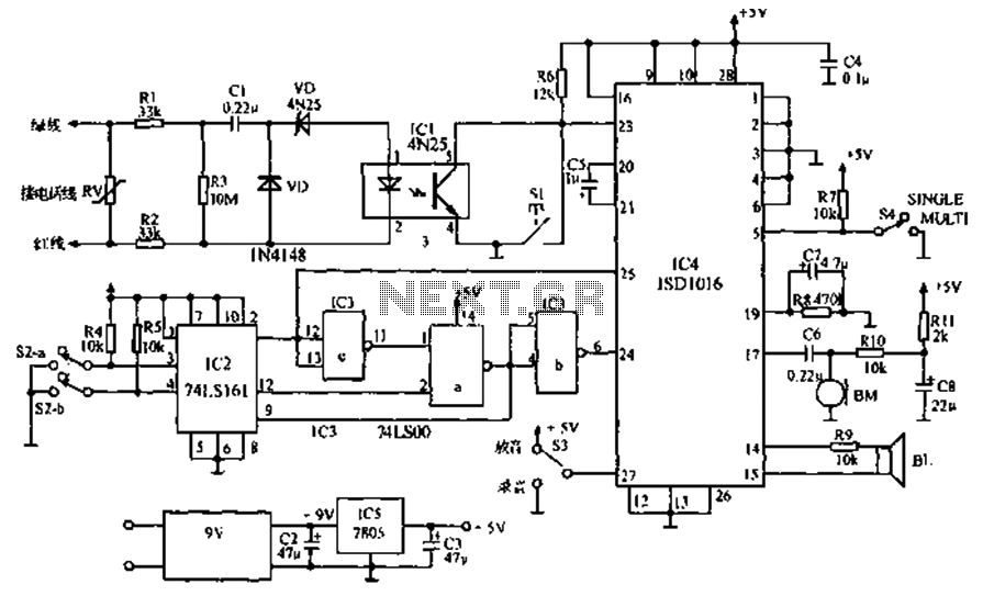
The call is made using the ISD1016 language chip for voice generation instead of a traditional phone ringing message controller schematic circuit. This controller can store messages, music, songs, or other sounds, serving as an alternative to monotonous ringing. The...
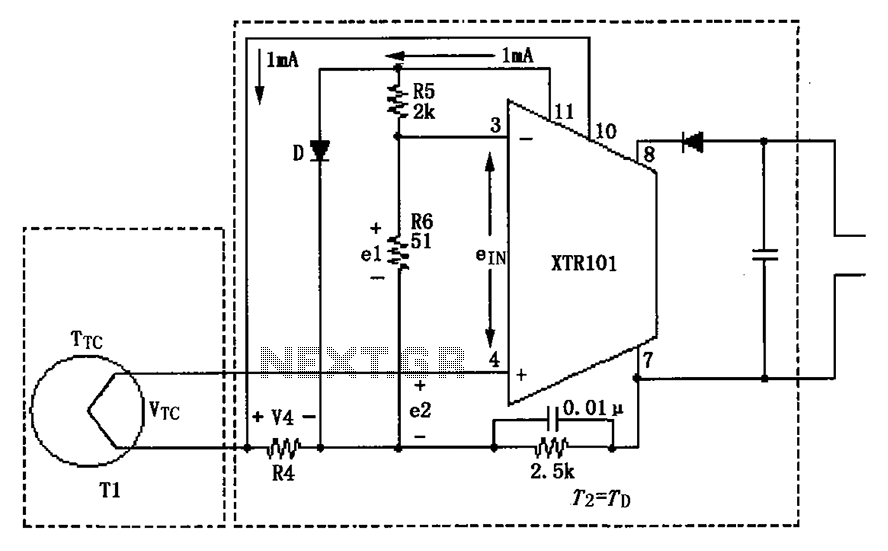
The circuit illustrated in the figure features two temperature zones and incorporates a thermocouple cold-junction compensation diode input circuit. It utilizes a J-type thermocouple as the temperature sensor. A semiconductor diode (D) is configured to provide cold junction compensation...
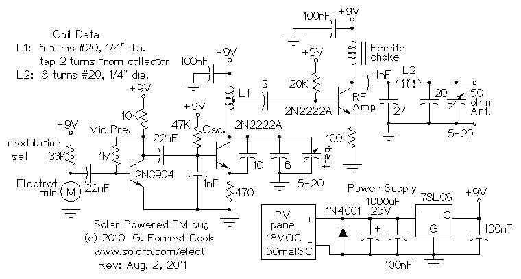
Here are some utility circuits for use with the Ramsey FM10a, and other small FM stereo transmitter kits. This information may be helpful for setting up a micro powered FM radio station. The FM10a and similar kits tend to...