
2 channel RF remote control

The transmitter comprises an AT90S2323 microcontroller and a TLP-418A RF transmitter module, operating at 418 MHz. The design focuses on battery conservation and secure data transmission. Battery conservation is achieved through the power-down mode of the AVR microcontroller, which reduces current consumption to less than 1 µA while in sleep mode until an external interrupt on pin PB1 wakes it. Pressing the S2 key pulls this pin low, waking the AVR, which then checks the S1 key. If S1 is not pressed, S2 is assumed to be pressed. The AVR then calculates a checksum and transmits a 4-byte sequence four times to ensure reliable data reception by the receiver before returning to sleep mode until the next interrupt.
The transmitted data consists of four bytes: the first two bytes serve as ID bytes for the receiver, the third byte is the command byte that determines the relay status, and the fourth byte is the checksum of the preceding three bytes. This results in a total of 32 bits of data without including start and stop bits, offering a theoretical possibility of over 4 billion unique combinations for the receiver to distinguish between different RF devices. The transmitter is compatible with all AT90S2323 chips, although the AT90LS2323 is preferred due to its lower operational voltage range of 2.7 to 6 volts. The microcontroller operates effectively with a 3V lithium battery.
The receiver consists of an RLP-418A RF receiver module, also operating at 418 MHz, paired with an AT90S2313 microcontroller and two relays capable of handling electrical loads up to 10 Amps at 250 Volts. The RLP-418A module uses Amplitude Shift Keying (ASK) modulation and provides both digital and analog outputs, though only the digital output (0V to VCC, which is 5V in this case) is utilized. The transmitter sends the 4-byte data sequence at 2400 bps, which the RLP-418A collects and transmits to the AT90S2313 via the RxD pin (PD0).
The AT90S2313 microcontroller employs a hardware UART configured for 2400 bps, which offers greater stability and efficiency compared to a software UART, particularly in handling data without loss during other routine operations. Upon powering the receiver and pressing the S1 key on the transmitter, the relay connected to PB0 on the receiver is activated. Pressing the S1 key again deactivates the relay. Similarly, pressing the S2 key on the transmitter activates the relay connected to PB1 on the receiver, with subsequent presses toggling its state. This design provides a reliable means of controlling devices remotely through RF signals.The basic small-range remote controls are 2, Infrared and RF (Radio Frequency). One of the weaks of Infrared is that the signal can not pass the walls. So, if you wantto control your garage door, the only way is to use some RF remote control. The circuit (transmitter and receiver) uses few components and ordinary (I love few component circuits). It`s easy to be built because you don`t have to tune-up any coil or variable capacitor. The RF modules are fix to work in 418MHz area. b. ) and thepower-saving of thetransmitter. Atransmitter must havelong battery life. It`s not the bestchoice for youto change the battery every 3 days ;). I don`t care about the receiver`s power supply, because receiver must beworking all the time. The transmitter is constituted by AT90S2323 microcontroller and TLP-418A RF transmitter module that works at 418MHz. I have designed the transmitter for more battery conservationand safe transmission of the data. The battery conservationwas madeby using thepower-down mode of AVR. In this case the AVR goes to sleep with less than 1uA (microampere) current and wait for external interrupt on pin PB1 to awake from sleep mode and continue operating.
If you press the S2 key, the logic of this pin goes to `0` (0V) and AVR awake from the sleep mode (because PB1 is INT0) andcheck if pressed the S1 key. If not, the AVR take as pressed key the S2. If yes the AVR take as pressed key the S1. Then, it calculates the checksum and transmits 4 times the same 4byte sequence to make sure that receiver will take the data and goes to sleep mode until next interrupt on PB1 pin.
The transmitted data has4 bytes length and is transmittedwith2400 bps (bits per seconds). The 1st and 2ndbyte are for the recognition of a valid remote control from the receiver (like ID bytes), 3rd byte is thecommand byte. The relays status is dependentby the value of this byte. Finally, the 4th byteis the checksum of the previous3 bytes. This method use 4 bytes x 8 bit each = 32 bit length (without start and stop bits). That is mean1 possibility at 4. 294. 967. 295 to receive the receiver, the same 4 bytes from some otherRF device. This transmitter works with all AT90s2323 chips but better is AT90LS2323 with working voltage 2. 7 - 6 volts. The microcontroller that I use is AT90S2323 with working voltage 4 - 6 volts. Its worked fine with 3v lithium battery. The receiver is constituted by RF receiver module RLP-418A at 418MHz, the microcontroller AT90S2313 and the 2 relays whichcan handle any electric (or electronic) device up to 10 Amps (the contacts of my relays are 10Amp at 250Volts).
The RLP-418A is an RF receiver module that works at418MHz withASK modulation. There are 2 outputs from this module, the digital, with levels from 0v toVCC (5 volts in our case) and the analog output. Analog output is not used. The transmitter sends 4 bytes with 2400 bps 4 times and the receiver RLP-434A, collect them andmove them toAT90S2313 throughRxD pin, PD0.
a. ) AT90S2313 uses a hardware UART adjusted at 2400bps andthe hardware UART is more stable, withsmallercode, than software UART that I use in the transmitter. If some serial dataarrives inthe middle-time of some other routine otherthan receive routine, we will loose these bits of data for sure.
The hardware UART does not have this problem because has hardware buffer for this function (UDR register). This is whatI mean when I say thatthehardware UART is"stable". Power on the receiver and press S1key on thetransmitter. You will see that the relay on PB0of the receiver will be armed. If you press one more time the same key, the relay will be disarmed. If you press S2key fromtransmitter you will see that relay on PB1of receiver will be armed. If you press one more time the same k 🔗 External reference
Related Circuits
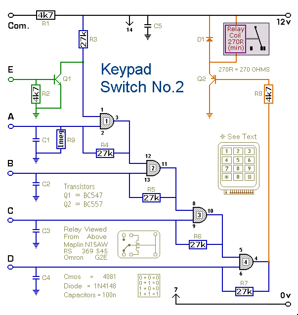
This is a simplified version of the 4-Digit Keypad Controlled Switch. The design has been modified to reduce the complexity of the circuit and the number of components required. Consequently, the code may be somewhat less secure; however, it...

The LTC 4251B, LTC4251B-1, and LTC4251B-2 are negative voltage Hot Swap controllers that facilitate the safe insertion and removal of a board from a live backplane. Output current is regulated through three stages of current limiting: a timed circuit...
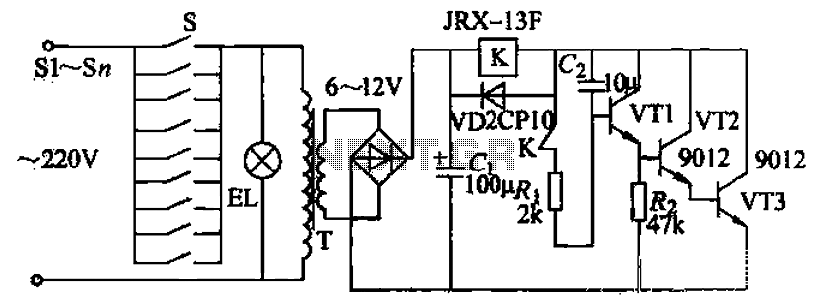
Pressing the button switch Sl-Sn activates the circuit, turning on the transformer T. The low-voltage alternating current from the secondary winding is directed to a bridge rectifier and a filter capacitor Ci, which produces a DC voltage. This voltage...
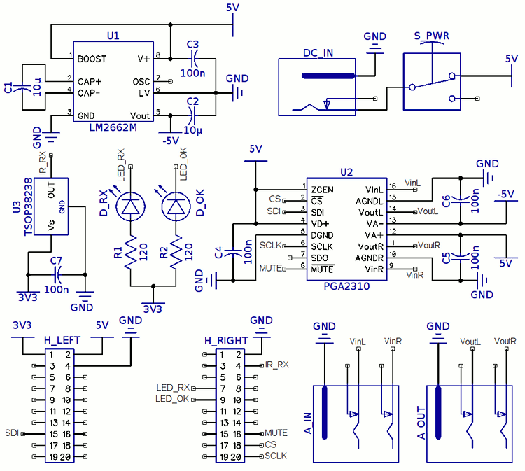
The television screen used at home features built-in speakers; however, since it functions as a computer display, it lacks an infrared receiver. This limitation prevents volume adjustment using the TV receiver remote. A recent acquisition of Stellaris LaunchPad development...
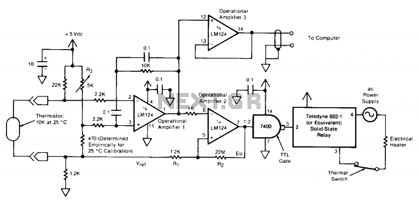
The circuit switches the current to an electrical heater on and off to maintain the temperature of a room at 25 ±0.5°C. The temperature sensor is a thermistor that provides a differential input (for reduced noise) to an operational...
An initial post to share work on remotely controlling the PXA-70x Multimedia controllers. The target for the new installation is under consideration. The PXA-70x Multimedia controllers are sophisticated devices used in various audio-visual setups, often found in automotive and home...