
Keypad Controlled Switch No2 circuit

The 4-Digit Keypad Controlled Switch is an electronic circuit designed to enable or disable a load based on a user-defined 4-digit code input through a keypad. The circuit typically consists of a 4x4 matrix keypad, a microcontroller, and a relay or transistor switch to control the load.
The matrix keypad is connected to the microcontroller's digital input pins. When a key is pressed, the microcontroller detects the specific row and column that intersect at the pressed key, allowing it to identify which digit has been entered. The microcontroller is programmed with the desired 4-digit code, which is stored in its memory.
The circuit operates in the following manner: upon powering up, the microcontroller remains in a standby mode, waiting for input from the keypad. When the user enters a sequence of four digits, the microcontroller compares the entered code against the stored code. If the entered code matches the stored code, the microcontroller activates the relay or transistor switch, which in turn allows current to flow to the connected load, effectively turning it on. If the entered code does not match, the circuit remains inactive, and the load stays off.
For security purposes, the design can incorporate features such as a timeout period after a certain number of incorrect attempts, during which the circuit would lock out further attempts for a predefined duration. While this simplified version may sacrifice some security features, it remains functional for applications where high security is not paramount.
Overall, this circuit is suitable for various applications, such as controlling lights, motors, or other electronic devices in home automation systems, providing a user-friendly interface for operation.This is a simplified version of the 4-Digit Keypad Controlled Switch. I have modified the design to reduce the complexity of the circuit - and the number of components required. As a result - the code is somewhat less secure. However, there should be lots of situations where it will still be adequate.. 🔗 External reference
Related Circuits
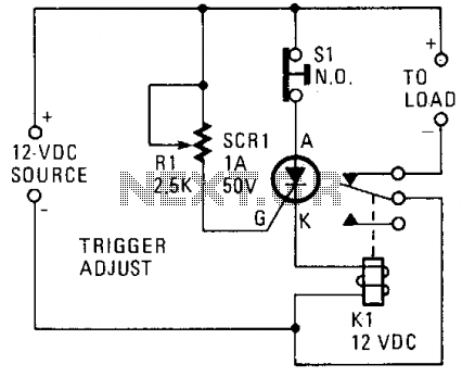
A silicon-controlled rectifier (SCR) is connected in parallel with the 12-V line and linked to a normally-closed 12-V relay, designated as K1. The gate circuit of the SCR is utilized to monitor the applied voltage. While the applied voltage...
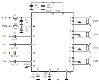
The TDA7383 features a fully complementary PNP/NPN output configuration, enabling a rail-to-rail output voltage swing without the need for bootstrap capacitors. This design significantly reduces the component count, allowing for compact assemblies. An integrated clipping detector facilitates gain compression...
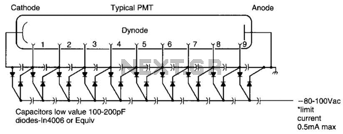
A Cockcroft-Walton voltage multiplier provides the necessary stepped voltage for the dynodes of the photomultiplier tube (PMT) without the use of a power-wasting voltage-divider resistor, which is typically employed in traditional configurations. The Cockcroft-Walton voltage multiplier is a type of DC-DC...
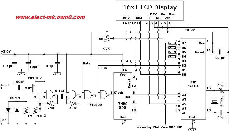
Frequency meter circuit for service applications, including all standard frequency bands: amateur HF, VHF, and UHF, displayed on an LCD screen. The frequency meter circuit is designed to accurately measure and display frequency across various amateur radio bands, specifically HF...
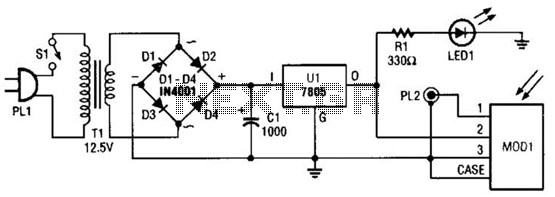
A schematic diagram for the remote analyzer is presented. The circuit is powered by a simple 5-V supply, which includes components such as PL1, SI, Tl, a bridge rectifier formed by diodes D1 through D4, capacitor CI, and a...
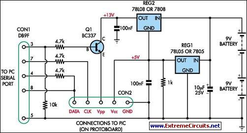
This simple programmer accepts any device supported by software. The circuit is partially based on the ISP header described in the SILICON CHIP "PIC Testbed" project and features an external programming voltage supply for laptops and other situations where...