
ir volume control

The circuit design integrates several key components to facilitate volume control in a television system lacking an infrared receiver. The microcontroller on the Stellaris LaunchPad serves as the core processing unit, receiving IR signals through the Vishay TSOP38238 infrared receiver. This receiver detects commands from the TV remote, interpreting them to control the volume levels. The PGA2310 chips are pivotal in managing audio attenuation, allowing for precise volume adjustments without introducing noise or artifacts into the audio signal. The use of zero-crossing detection ensures that changes in volume occur at the optimal moment in the audio waveform, thus maintaining sound quality.
Power management is efficiently handled through the TI LM2662 charge pump, which generates the necessary negative voltage supply required by the PGA2310. This design choice simplifies the power requirements, enabling the circuit to operate effectively from a single 5V source. The dual-layer PCB not only provides structural support but also facilitates organized routing of connections, reducing the risk of interference and ensuring reliable operation of the circuit.
The software component of the project is designed to decode the incoming IR signals and control the PGA2310. The IRMP library is utilized for decoding, supporting a wide range of protocols and enhancing the flexibility of the design. The integration of the SPI module on the LaunchPad allows for seamless communication with the PGA2310, ensuring that volume adjustments are executed promptly upon receiving the appropriate IR command.
Overall, this project exemplifies the integration of microcontroller technology with audio processing components to create a functional and user-friendly volume control solution for televisions lacking built-in infrared receivers. The combination of hardware and software components, along with careful attention to power management and signal integrity, results in a robust and effective circuit design.The screen that we watch TV on at home has build-in speakers, but, because it`s actually a computer display, hasn`t got an infrared receiver. This made it impossible to set the volume with the TV receiver remote. I recently bought some Stellaris LaunchPad development boards and figured this was the perfect opportunity to make something useful with
one. The idea is to receive and decode IR signals with a microcontroller and increase or decrease the volume with a digital volume control when the correct command is received. The inputs to the volume control come from the headphone out of the TV, the outputs go to a pair of active speakers.
I decided to build my circuit around a development board I recently bought from Texas Instruments for a discount price of ‚¬4. 20. It`s a Stellaris LaunchPad, which sports an ARM Cortex-M4F (TI LM4F120H5QR) that can run at up to 80 MHz.
There`s a build-in USB debug interface on the board, and in- and outputs are provided on two 2G—10 headers. In high school, I designed a few audio circuits and I had some TI PGA2310 chips lying around from back then.
These are high quality 8-bit digital audio volume controllers with zero crossing detection. This means that they switch the volume when the audio signal is at 0V, so that there`s no audible pop from the speakers. For the infrared receiver, I used a Vishay TSOP38238, which has a built-in filter for reception of 38 kHz signals, the frequency at which most TV remotes work.
I wanted to use a cheap 5V power brick to power this circuit, and the PGA2310 requires at least 4. 5V as its positive supply, so splitting the 5V into ±2. 5V was out of the question. Instead, a charge pump, the TI LM2662, is used to generate -5V. This IC requires just two external capacitors in order to invert its positive supply voltage to a negative output voltage. Those chips, with a healthy dose of LEDs sprinkled on top for user feedback form the hardware part of the circuit.
You can find the schematic below. The circuit was build on adual-layer prototyping PCB I got on eBay. Most of the components are though hole, but I used SMDs whenever I could (e. g. for all the capacitors). The LaunchPad board plugs neatly on top of this. I added a small 3 pin header to the underside of the LauchPad in order to be able to use its on-off switch for the supply voltage. Below are a few pictures of the result. There are so many wires on the bottom of the board because all ground connections are tied to a central star ground connection.
Putting the hardware together only took a single evening. Getting the software for the microcontroller to work though, took me quite a bit longer. First of all I had to get the IDE setup, which is quite straightforward, but still takes a while. Luckily, I found a great set of tutorials on how to set up a toolchain, debugger and IDE for the Stellaris LaunchPad on linux on the Kernel Hacks blog. Unfortunately, I did not get the debugging working perfectly. In hindsight, it probably would have saved me a ton of time if I had. The software itself consists of two parts: decoding incoming IR signals and setting the attenuation of the PGA2310.
In order to correctly decode the IR signals, you have to know which protocol is used by the IR remote. Since I couldn`t find any information on my remote, I decided to use the IRMP library (site in German).
This is a really nice, highly configurable piece of software that supports 30+ protocols, hash build in hooks for debugging, Interfacing with the PGA2310 only required setting up the LaunchPad`s SPI module. Although integrating IRMP, the SPI interfacing and the tiny bit of logic required in little time, the software would run haphazardly on the LaunchPad.
After many evenings of debugging and trying different build options, it seemed that the problem was due to stack corruption. Switching to the linker script provided by eehusky on his GitHub repository solved the pr 🔗 External reference
Related Circuits
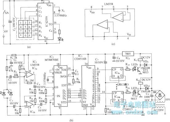
Figure (a) illustrates an infrared emission circuit composed of a 12-key keyboard and an S2559. Figure (b) displays a DTMF decoder circuit along with a channel control circuit utilizing the MT8870. Figure (c) presents a voltage amplifier circuit constructed...

Design a low-cost 4- to 20-mA receiver circuit for control loops using an analog-to-digital converter (ADC). The design of a low-cost 4- to 20-mA receiver circuit is essential in industrial applications for monitoring and controlling processes. This current loop standard...
The automatic sprinkler controller circuit consists of a power supply circuit and a humidity measurement and control circuit, as illustrated in the accompanying figure. The power supply circuit includes a power transformer (T), rectifier diodes (VD1 to VD4), filter...
The latest addition to the collection of Infrared (IR) Repeater circuits, the Mark 5, is a significantly enhanced version of the Mark 1 circuit, featuring improved range and sensitivity. It is designed to be immune to the effects of...
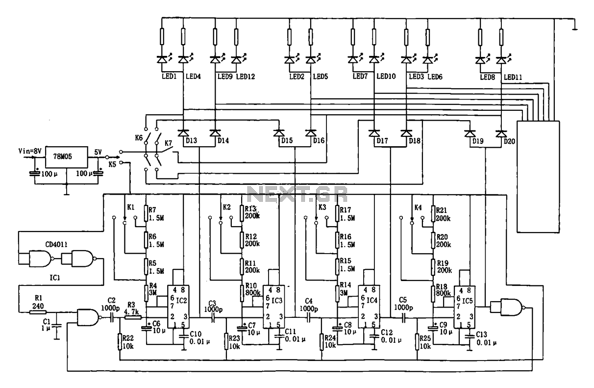
This document describes an automatic traffic intersection light control circuit. It features four monostable delay circuits, which consist of four 555 timer integrated circuits (IC2 to IC5) and several RC components interconnected. An 8V input voltage is regulated through...

The term VCXO refers to a Voltage Controlled Crystal Oscillator. The frequency of this oscillator can be fine-tuned by varying the control voltage. VCXO clock generators are utilized in a range of applications, including digital telecommunications. VCXO circuits are essential...