
2 LED CMOS Flasher

The two LED CMOS flasher circuit utilizes the CD4069 integrated circuit, which contains six inverters, to create a multivibrator configuration. This circuit is designed to flash two LEDs alternately, providing a visual indication of the oscillation created by the inverter gates.
In this configuration, two of the six inverters are employed to form a basic astable multivibrator. The circuit operates by charging and discharging capacitors, which control the timing of the LED flashes. The LEDs are connected to the output of the inverters, allowing them to turn on and off in succession.
The key components of the circuit include:
1. **CD4069 IC**: This is a hex inverter that provides the necessary logic levels for the multivibrator operation.
2. **Resistors**: Used to limit current to the LEDs and to set the charging and discharging time constants for the capacitors.
3. **Capacitors**: These components are crucial for determining the frequency of the flashing LEDs by controlling the timing intervals.
4. **LEDs**: Light Emitting Diodes that visually indicate the output states of the circuit.
The circuit is powered by a DC voltage source, typically ranging from 3V to 15V, depending on the specifications of the LEDs and the CD4069. The values of the resistors and capacitors can be adjusted to change the frequency of the flashing LEDs, allowing for customization of the visual output.
Overall, this simple yet effective circuit serves as an excellent introduction to basic CMOS technology and multivibrator design, demonstrating fundamental principles of electronics in a practical application.Two LED CMOS Flasher Circuit Diagram This is a simple 2 led cmos robot ( flasher, multivibrator ) circuit using CD4069 six inverter.. 🔗 External reference
Related Circuits
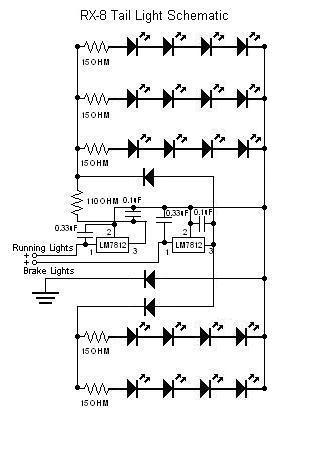
The circuit has been successfully recreated and functions properly when the line connected to the 1 µF capacitor of the "2" terminal of the running lights' LM7812 is not grounded. This line is also connected to the 33 µF...

Efficiency can be increased by using a germanium transistor at the 33 ohm current sense resistor, and by using a proper torroid core in place of the crappy ferrite bead. Single AA cell powers two LEDs at constant current. The...

This document presents a collection of compact, self-contained alarm circuits. These circuits are designed to operate with a very low standby current, making them ideal for battery-powered applications. They can be triggered by both normally-open and normally-closed switches, while...
Watching the time on a mobile phone in the dark can cause discomfort due to the strong contrast between bright and dark backlighting. To address this issue, the "ICON" model is utilized, which operates in standby mode with a...
A switch that is controlled by its ambient temperature operates without human intervention, except during the assembly of the electronic thermostat. This thermally controlled switch has numerous practical applications. For instance, if the internal temperature of a computer rises...

This temperature-controlled relay circuit is a simple yet highly accurate thermal control circuit that can be used in applications requiring automatic temperature regulation. The temperature-controlled relay circuit operates by monitoring the ambient temperature and activating or deactivating a connected load...