
2 module ir light barrier wont run same power source

The circuit involves a transmitter and receiver setup designed to communicate via infrared signals. The transmitter is equipped with an IR LED that emits light when powered, while the receiver is sensitive to variations in light intensity, specifically detecting the presence or absence of the IR light to determine whether a signal is being received.
The inclusion of a 0.1µF capacitor serves as a high-frequency bypass capacitor, filtering out high-frequency noise that may interfere with the operation of the transmitter and receiver. The 500µF electrolytic capacitor is intended to stabilize the power supply by providing a reservoir of charge, smoothing out fluctuations in voltage that can occur during operation.
The use of decoupling capacitors across the power supply lines is critical for maintaining signal integrity, especially in sensitive electronic applications. These capacitors help to reduce voltage spikes and dips that can affect the performance of the circuit. The recommendation to use a 10Ω resistor in series with the receiver is aimed at isolating it from potential noise generated by the power supply or the transmitter, thereby enhancing the reliability of the signal detection.
The 1000µF capacitor located near the buzzer in the receiver circuit is intended to filter out low-frequency noise, ensuring that only relevant signal variations are detected. This is particularly important in environments where electromagnetic interference is present, as it can lead to false triggering or failure to detect the intended IR signal.
The dual mode power supply configuration, with one supply connected to a transformer without a load, raises concerns about the stability of the voltage supplied to the circuit. The blown fuse indicates that there may be an overload condition or a short circuit somewhere in the system, necessitating a review of the circuit design and component ratings, including the LM338 voltage regulator, to ensure proper operation under all conditions.
Testing with a 9V battery and a 10Ω resistor provides a simplified method to evaluate the basic functionality of the transmitter and receiver. The observation that the IR LED is visible with a digital camera confirms that the transmitter is operational, but further troubleshooting is required to identify the cause of the failure in the receiver's response. This may involve checking connections, verifying component values, and ensuring that the receiver is correctly positioned to detect the IR light from the transmitter.Connected 0. 1uf cap and 500uf electrolytic cap to transmitter and the same to receiver. The result was it still does not work. I tried to add just diodes but it did not help either. when u say it doesent work-what is happening when the ir is recieved by the rx unit-what happens when no ir is recieved a scope would be handy here to see exactly what is happening when the two units are powered up but add decoupling caps across the supply for both units -what type of supply are u using to power them it may be that which is causing the problem. when u say it doesent work-what is happening when the ir is recieved by the rx unit-what happens when no ir is recieved a scope would be handy here to see exactly what is happening when the two units are powered up but add decoupling caps across the supply for both units -what type of supply are u using to power them it may be that which is causing the problem.
I`m using this PSU, in dual mode meaning the other PSU was conected to transformer with no load. I did blow my fuse 250mA at the transformer for some reason. I wonder if the fuse rating is correct and if LM338 needs a dummy load, remember I have dual PSU The receiver is just looking for any variation in light levels, and it will also operate when there is noise on the power supply. That will make it fail to detect a break in the beam. Power supply noise could come from the power supply or from the transmitter. Either way, you should isolate the receiver from that noise with something like a 10 © resistor in series, close to the receiver.
That, along with the 1000 µF capacitor in the receiver (C5, shown near the buzzer) should remove noise at the frequencies that the receiver is sensitive to. The receiver is just looking for any variation in light levels, and it will also operate when there is noise on the power supply.
That will make it fail to detect a break in the beam. Power supply noise could come from the power supply or from the transmitter. Either way, you should isolate the receiver from that noise with something like a 10 © resistor in series, close to the receiver. That, along with the 1000 µF capacitor in the receiver (C5, shown near the buzzer) should remove noise at the frequencies that the receiver is sensitive to.
I tried to take single battery 9V add resistor 10 © in series to the receiver and power both circuits. The result is it does not work. With digital camera I can see transmitter IR LED on both ways with single battery and on separate batteries.
🔗 External reference
Related Circuits
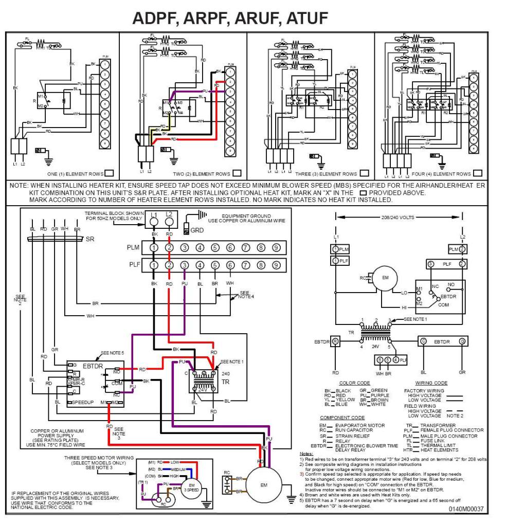
A Goodman Janitrol 2.5-ton Standard Air Handler, model #ARUF030-00A-1, was diagnosed with a malfunction where the fan could only be turned off by either switching off the breaker or disconnecting the black wire leading from the fan to the...
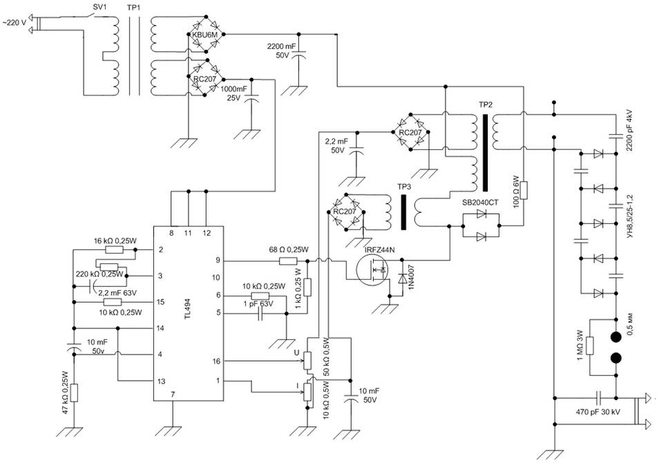
The schematic diagram is derived from the circuit of a High Voltage Power Supply utilizing the PWM IC TL494. This power supply requires a suitable alternating voltage source of 12 V / 800 mA. An alternating voltage is rectified...
The circuit safely delivers approximately 20 Amps at 13.8V. For lower current applications, a separate current limiting output capable of 15mA up to a total of 20A has been included. The power transformer should be able to supply at...
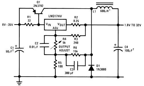
The circuit diagram of this LM317 power supply electronic project requires a few external components. The input voltage for this project must be between 8 and 35 volts, providing a variable output voltage ranging from 1.8 volts to 32...
IC4, C1, R1 and R2 are used for the clock pulse which is fed to both the counters IC2 and IC3 Pin 14. IC1 is a Flip Flop and is used as a switch to enable either IC2 or...
If 40 watts RMS from 20Hz to 30KHz +/-1.5 dB is appealing, this experiment may be of interest. A significant issue with public address equipment is the use of audio output transformers that lack sufficient iron to manage lower...