
lm317 variable power supply circuit project

The LM317 is a popular adjustable voltage regulator that is widely used in power supply applications due to its versatility and ease of use. The input voltage range of 8 to 35 volts allows for compatibility with various power sources, making it suitable for a range of applications. The output voltage can be adjusted by changing the resistor values in the feedback network connected to the LM317, enabling a wide range of output voltages from 1.8 volts to 32 volts, suitable for powering different electronic devices.
Capacitors C1 and C4, specified as solid tantalum types, play a crucial role in stabilizing the voltage output and filtering noise. Tantalum capacitors are known for their reliability and stability over a wide temperature range, making them ideal for this application. The use of a 600 µH inductor (L1) in the circuit is essential for smoothing out the output voltage and minimizing ripple, ensuring a stable supply for the connected load. The recommended Arnold A-254168-2 core with 60 turns provides the necessary inductance while maintaining compactness and efficiency in the design.
Overall, this LM317 power supply circuit is a robust solution for providing adjustable voltage outputs, with careful consideration given to component selection for optimal performance and reliability.As you can see in the circuit diagram this LM317 power supply electronic project require few external components. The input voltage required by this electronic project must be between 8 and 35 volt, and will provide a variable output voltage over a wide range, from 1.
8 volts up to 32 volts. C1, C4 capacitors must be a solid tantalum type and L1 coil must have a 600uH inductance. For L1 coil you can use a Arnold A-254168-2 core with 60 turns. 🔗 External reference
Related Circuits
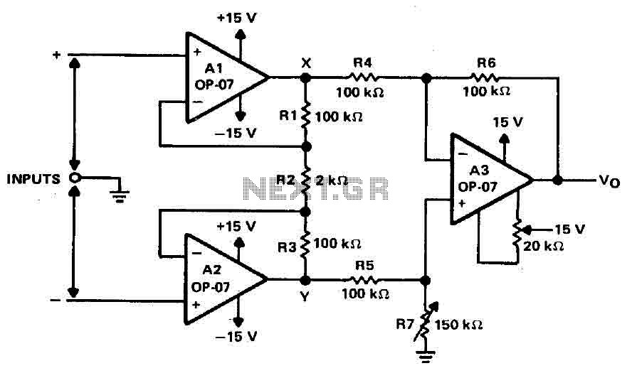
Operational amplifiers A1 and A2 are connected in a non-inverting configuration to form amplifier A3. The operational amplifier A3 can be classified as a subtractor circuit that converts the differential signal between the floating points X and Y into...
The most extreme option would be to supply power through a battery pack. A more plausible source would be the car's battery. However, since the objective of the circuit is to activate the buzzer when the headlights are on,...

This circuit was designed by Lazar Pancic from Yugoslavia. A typical PC sound card includes a microphone input, speaker output, and occasionally line inputs and outputs. The microphone input is specifically tailored for dynamic microphones with an impedance range...
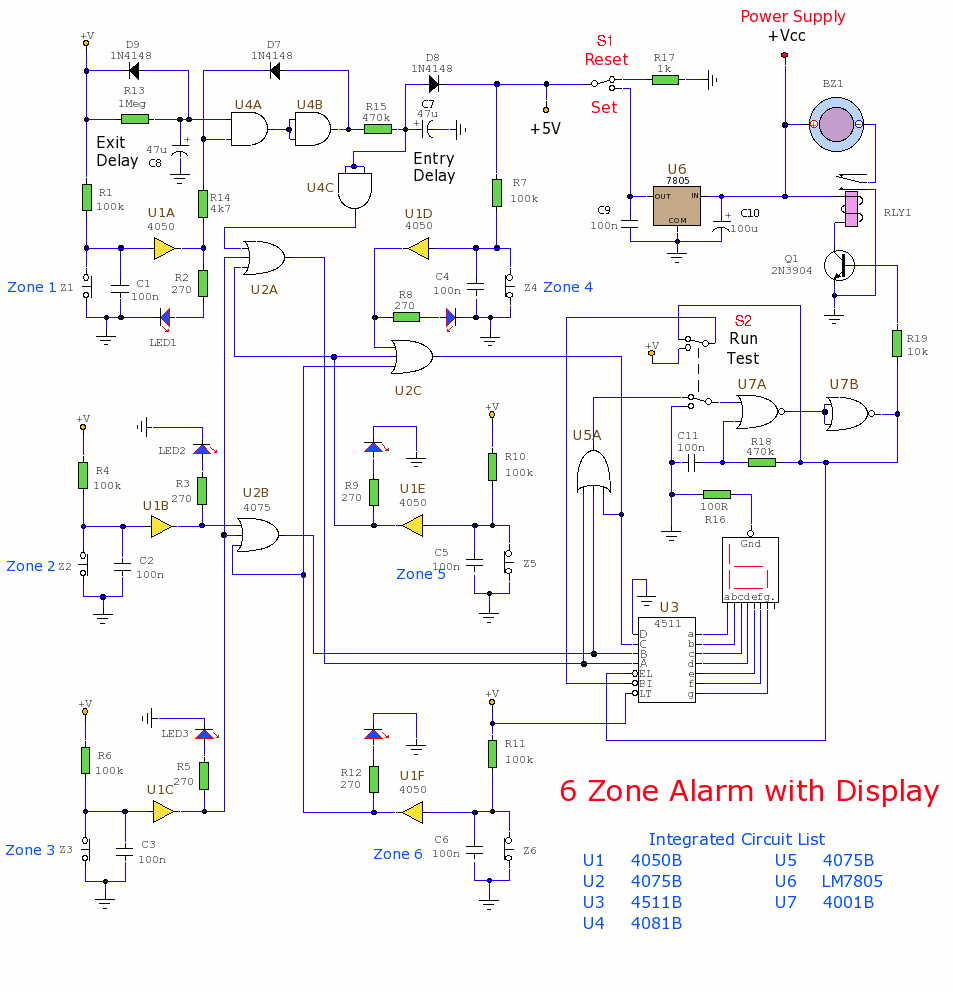
This section includes intruder alarms for homes, cars, and motorcycles, as well as power failure alarms, water level alarms, and a snore detector. All circuits are organized alphabetically on the Circuit Index page and chronologically on the update page....
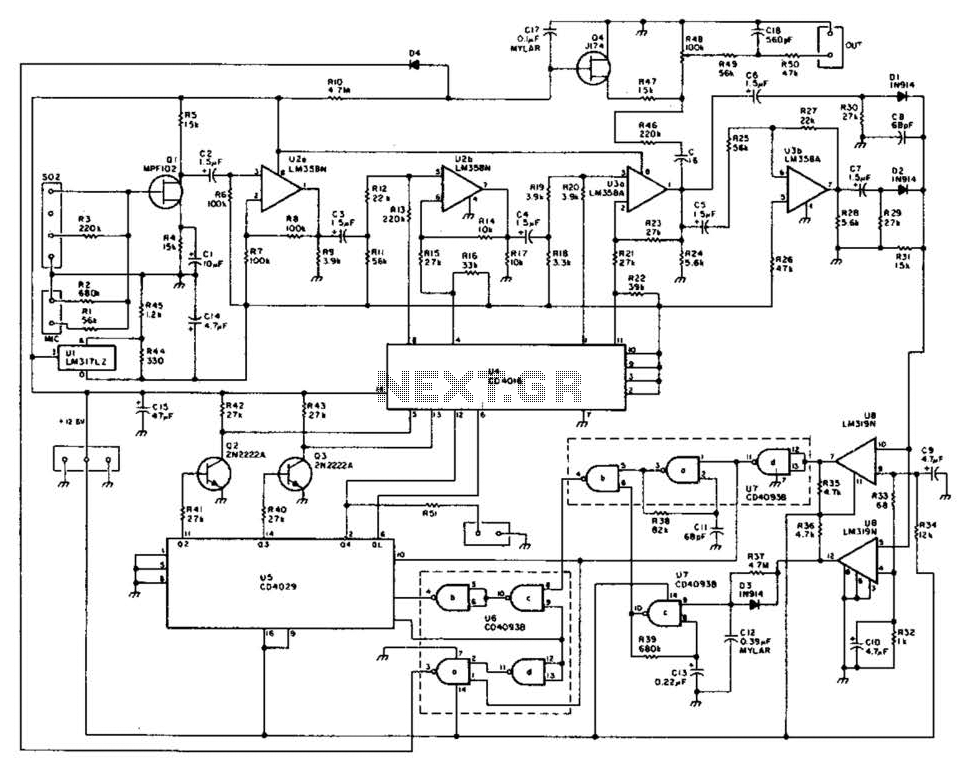
This method of automatic level control (ALC) utilizes digitally switched audio attenuators within the signal path. The output level of the system is monitored, compared to a reference level, and audio pads are introduced through analog switches. This technique...
This document details the AT Keyboard Interface and AT Keyboard Protocols. It includes an example of a Keyboard to ASCII decoder utilizing a 68HC705J1A microcontroller. The AT Keyboard Interface is a standard communication protocol used primarily in personal computers to...