
Nite Rider LED Lights

The circuit utilizes a 555 timer (IC4) configured in astable mode to generate a continuous clock pulse. This clock pulse is essential for driving the two decade counters (IC2 and IC3, both 4017 types) located at pin 14, allowing them to count in a sequential manner. The flip-flop (IC1, 4027) functions as a toggle switch, enabling the selection of either counter IC2 or IC3 through its output at pin 13. This setup allows for flexible control over which counter is active at any given time.
The counters are designed to count from 0 to 9, with their outputs available at respective pins. The circuit includes a detection mechanism using IC7a, which monitors the Q9 output (pin 11) of the counters. When either counter reaches this state, it signals that the counting cycle has completed.
To protect the output signals from the counters, three OR gates (IC5, IC6, and IC7, all 4071 types) are employed. These gates ensure that the outputs from both counters are combined and can drive the anodes of the nine super bright LEDs (1 to 9), illuminating them based on the counting state. The choice of LED color can vary, with suggestions for red LEDs for rear visibility and white LEDs for enhanced visibility at the front of the bike.
The circuit is powered by a 9V PP3 battery, which is suitable for the CMOS technology used in all ICs, ensuring low power consumption. This design consideration allows for extended battery life, making the circuit practical for long-term use. Additional components include resistors (R1 and R2, both 10K ohm, and R3, a 470 ohm) and a capacitor (C1, 6.8µF, 16V) to stabilize the clock signal. A single-pole switch (SW1) is also included for manual control of the circuit's operation. The entire assembly can be housed within a suitable enclosure for protection and aesthetics.IC4, C1, R1 and R2 are used for the clock pulse which is fed to both the counters IC2 and IC3 Pin 14. IC1 is a Flip Flop and is used as a switch to enable ether IC2 or IC3 at pin 13. IC7a detects when ether IC2 or IC3 has reached Q9 of the counter pin 11. IC5, IC6 and IC7a protects the outputs of the counters IC2 and IC3 using OR gates which is then fed to the Anodes of the LED's 1 to 9.
It could be constructed with red LEDs for use on the rear of the bike or white LED's for an extra eye catcher on the front of the bike. All IC's are CMOS devices so that a 9V PP3 battery can be used, and the current drawn is very low so that it will last as long as possible.
Parts: 1 555 timer IC4. 1 4027 flip flop IC1. 2 4017 Decade Counter IC2 and IC3. 3 4071 OR gate IC5, IC6 and IC7. 1 470 Ohm resistor 1/4 watt R3. 2 10K resistors 1/4 watt R1 and R2. 1 6.8UF Capasitor 16V C1. 9 Super brght LED's 1 to 9. 1 9V PP3 Battery. 1 single pole switch SW1. 1 Box. 🔗 External reference
Related Circuits

The design of a PAR 38 LED spotlight focuses on delivering practical LED lighting systems that meet performance expectations by reducing power consumption, extending lifespan, and enhancing overall efficiency. The PAR 38 LED spotlight is a widely used lighting solution...
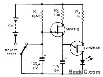
The following circuit illustrates a flashing LED egg timer circuit diagram. This circuit utilizes 2N2646 transistors and features an MPF112 FET. The flashing LED egg timer circuit operates as a visual timer, providing an indication of elapsed time through the...

The Keypad Controlled Switch No2 Circuit operates with a 12-volt supply but is compatible with voltages ranging from 5 to 15 volts. The only requirement is to select a relay that matches the desired supply voltage. The Keypad Controlled Switch...
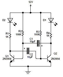
This is a 2 LED flashing circuit. It is based on an analog flip flop circuit. This particular circuit was calculated to use blue or white 3V LED with a 12V power supply. If you are using red green...

The low-cost and compact circuit presented here serves as a highly power-saving flashing LED indicator. While most LEDs typically fail to operate below 2 volts, with a forward voltage of at least 1.6 volts, this flasher can function using...
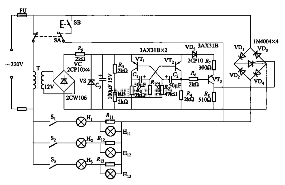
The self-excited multivibrator circuit utilizes transistors VTi and VT2 to generate an output signal that triggers a thyristor (VT3). An adjustment potentiometer (RP) is incorporated to modify the oscillation frequency, which in turn adjusts the flashing cycles of lights...