
2 small magnification difference between the balanced output circuit

A balanced output configuration in operational amplifiers is crucial for minimizing noise and distortion, especially in high-frequency applications. The positive phase output terminal of the operational amplifier serves as the primary output, while the inverting input creates a phase-reversed output. This configuration is essential for differential signaling, where the goal is to maintain signal integrity over long distances.
In practical implementations, the inverting amplifier circuit can experience issues such as DC offset drift, which can compromise the balance of the output signal. This drift can be exacerbated in wide-band signal applications where the frequency response is critical. To mitigate these issues, circuit designers often incorporate feedback mechanisms and compensation techniques that stabilize the output against variations in input frequency.
The design of a balanced output circuit typically includes precision resistors and capacitors to ensure that the frequency response remains flat across the desired bandwidth. Additionally, careful consideration must be given to the layout of the circuit to minimize parasitic capacitance and inductance, which can introduce additional phase shifts and distortion.
Overall, maintaining a balanced output in operational amplifier circuits is vital for achieving high fidelity in signal transmission, particularly in audio and communication systems. The careful design and implementation of these circuits ensure that even with varying input conditions, the output remains stable and free from phase distortion.A balanced output mentioned, people tend to immediately think of the positive phase amplifier output terminal increases 0P amplifier as the inverting amplifier circuit, normal and reversed phase output set to lose balance fH o in the DC circuit, although this method can be used, but as Tiao are wide -band signal, the inverting amplifier cup drift is a problem. Since this circuit. OP measures also zoom in and drift d is equal to the soil, so even if the input frequency of change seven phase distortion does not occur 4
Related Circuits
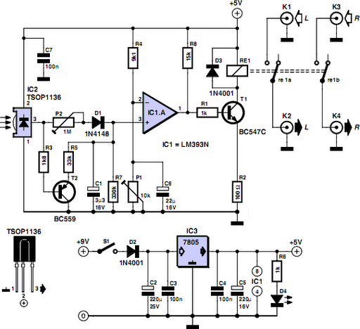
Many households still have tube-type television sets. Connecting one of these large televisions to a stereo system to enhance sound quality is generally straightforward, as numerous SCART to Cinch adapters are available in accessory stores. However, some television sets...
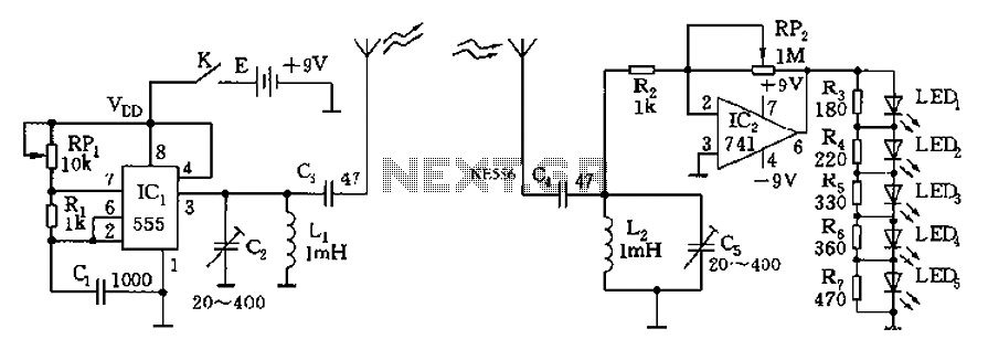
The circuit diagram of the device features a 555 timer IC configured as a transmitter and a receiver, divided into two sections. The 555 timer in the transmitter section serves as the core component of a frequency oscillator. The...
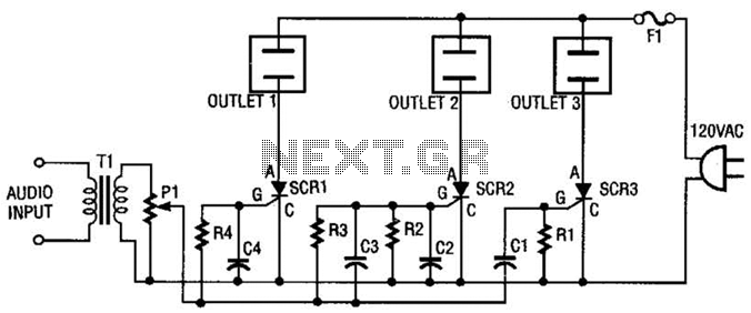
The AC line power is introduced into the circuit through F1, a protective 5-A fuse. One side of the AC line is connected to one side of each AC outlet, while the other side is connected to each silicon-controlled...
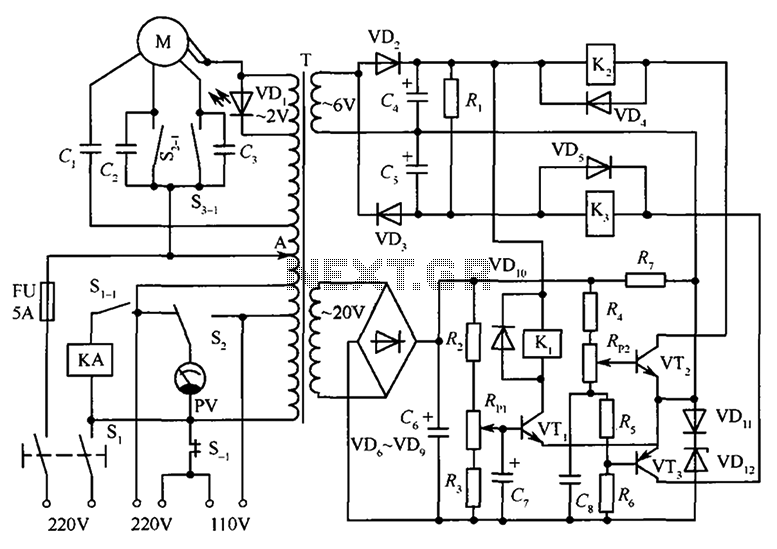
The circuit illustrated in the figure features an automatic voltage regulator (T) that utilizes a servo motor to ensure a constant output voltage. The transistors used are VT1 and VT2 (3DK9C, with a range of 65 to 85) and...
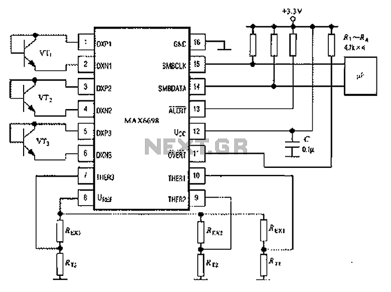
The circuit illustrated in the figure involves the MAX6698 maximum temperature sensor, which utilizes three transistors (VT1 to VT3) and three thermistors (RT1 to RT3). An internal reference voltage source is connected through resistors UREF REX1 to REX3, providing...
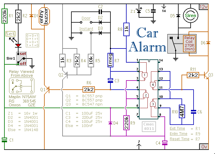
This car alarm circuit includes exit and entry delays, an instant alarm zone, an intermittent siren output, and automatic reset. By incorporating external relays, it is possible to immobilize the vehicle and activate the flashing lights. The car alarm circuit...