
3 Channel Color Organ Circuit
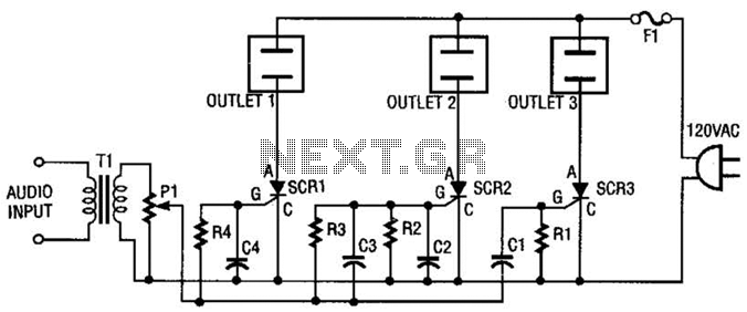
The circuit operates by first ensuring that the AC line power is safely managed through the 5-A fuse (F1), which protects against overcurrent conditions. The AC outlets are configured in parallel, allowing for multiple devices to draw power from the same source. The SCRs play a crucial role in controlling the power delivered to the outlets; they act as electronic switches that can be turned on or off based on the gate signal they receive from the RC filter stages.
The audio signal from the stereo speaker is transformed by T1, which steps down the voltage to a manageable level suitable for processing. The primary winding of T1, with its higher impedance, ensures that the signal is compatible with the circuit's input requirements. The connection of the 8-ohm side to the speaker allows for efficient signal transfer, while the 500-ohm side's connection to potentiometer P1 provides an adjustable sensitivity control. This potentiometer allows the user to modify the amplitude of the audio signal before it reaches the SCRs, enabling fine-tuning of the system's response to the audio input.
The RC filter stages connected to the gate leads of the SCRs are critical for frequency selection. Each SCR's gate is driven by a unique RC filter that determines its frequency response characteristics. As the capacitance value in the filter increases, the SCR will trigger at lower frequencies, allowing for selective activation based on the audio signal's frequency content. This design enables the circuit to respond dynamically to varying audio signals, making it suitable for applications such as audio level control, light dimming, or motor speed regulation based on audio input. The careful selection of resistor and capacitor values in each filter stage is essential for achieving the desired frequency response and ensuring optimal performance of the SCRs within the circuit. The ac line power is brought back into the circuit through Fl, a protective 5-A fuse. One side of the ac line is connected to one side of each ac outlet. The other side of the ac line is connected to each SGR or silicon-controlled rectifier. Each SCR is, in turn, connected to the other side of each ac outlet.An audio signal is brought into the circuit from a stereo speaker by transformer Tl. This transformer has 500- Impedance on the primary and 8- impedance on its secondary. Connect Tl so that the 8- side is connected to the speaker and the 500- side is connected to potentiometer PI.Potentiometer PI is used as a level or sensitivity control.
The signal from its wiper lead is applied to each RC filter stage. Because each SCR has a different RC (resistor/capacitor) filter on its gate lead, each will respond to different frequencies. The greater the capacitance in the filter, the lower the frequency that the SCR will respond to. 🔗 External reference
Related Circuits
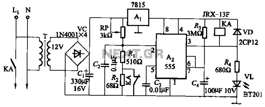
This circuit is applicable in refrigerators and other protective devices. It employs a 7815 three-terminal voltage regulator integrated circuit and an NE555 timer IC configured as a one-shot circuit for delay control. When the voltage drops below 180V, relay...
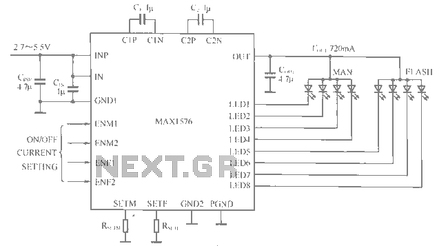
The MAX1516 charge pump drives up to 8 white LEDs with constant current regulation to achieve uniform light intensity, capable of delivering up to 30mA per LED for backlighting. The flash group LEDs (LED5 to LED8) are individually controlled,...
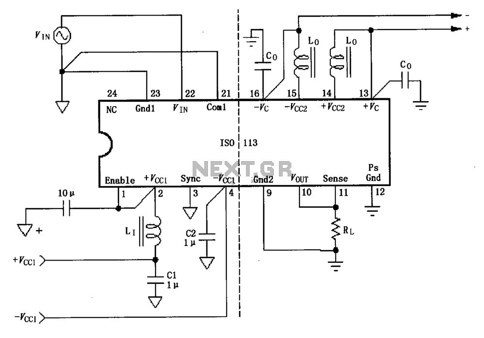
The basic connection circuit for the ISO113 signal and power supply is illustrated. Each power supply terminal must include a bypass filter. If the output current from the isolated power supply exceeds 15mA, it is advisable to utilize an...
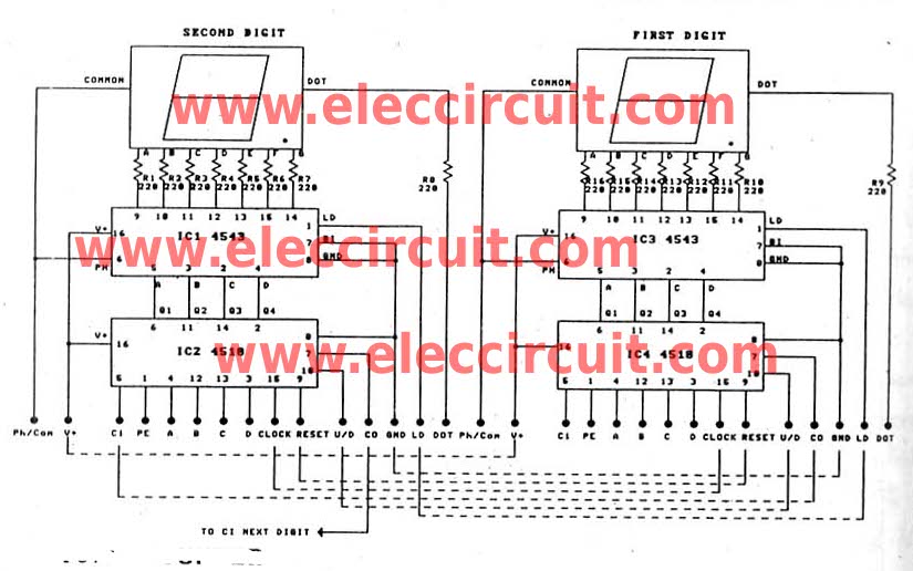
This is a versatile digital counter circuit that is cost-effective due to the basic components available in many electronic shops. The digital counter circuit is designed to count pulses and display the count on a digital readout, typically using a...
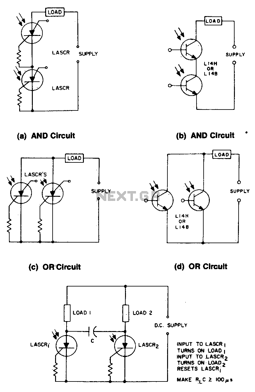
These circuits illustrate some of the common logic functions that can be implemented. The provided circuits serve as examples of fundamental logic functions utilized in digital electronics. Logic functions are the building blocks of digital systems, enabling the execution of...
Unfortunately, there is no breadboard available for testing; however, modifications can be made to the PCB. The 1K potentiometer has been removed until the strobe functionality can be established. The circuit in question appears to involve a strobe light mechanism,...