
FM Transmitter circuit diagram (50M) With 2N2222 Transistor
 With 2N2222 Transistor")
The FM transmitter circuit consists of several key components, primarily centered around the 2N2222 transistor, which serves as the main amplification element. The circuit is designed to operate within a voltage range of 3V, making it suitable for battery-powered applications.
The configuration typically includes a power supply connected to the collector of the transistor, while the base is driven by an audio input signal. This audio input can be sourced from various devices, such as microphones or audio players. A resistor is often placed between the base and the power supply to limit the current flowing into the base, ensuring the transistor operates within its safe limits.
The circuit utilizes a resonant LC circuit, which consists of an inductor and a capacitor, connected to the collector of the transistor. This LC circuit is crucial for determining the frequency of the transmitted signal. By adjusting the values of the inductor and capacitor, the operating frequency can be tuned to the desired FM band, usually between 88 MHz and 108 MHz.
A variable capacitor might be incorporated into the circuit to allow fine-tuning of the frequency, enhancing the transmitter's performance and enabling it to avoid interference with other signals. The output from the collector is then coupled to an antenna, which can be a simple wire, to radiate the FM signal over a distance of up to 50 meters, depending on the surrounding environment and the quality of the components used.
Overall, this FM transmitter circuit offers a straightforward and effective solution for low-power audio transmission, making it a popular choice for hobbyists and educational projects in the field of electronics.This is a FM transmitter circuit diagram. This circuit using 2N2222 Transistor so can be operated with 3V, and also can send signals up to 50m .. 🔗 External reference
Related Circuits
There are two regulator circuits that utilize the L200 integrated circuit from SGS-Thomson to regulate voltage and current. In circuit Fig. 1, the output voltage can be adjusted using the variable resistor RV1. In Fig. 2, both output voltage...
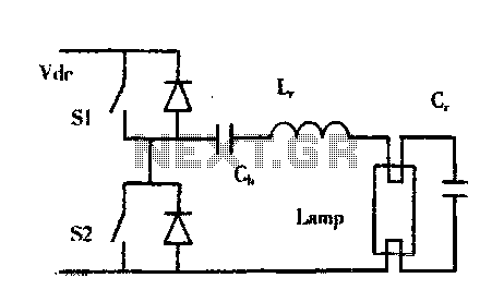
The construction of buildings, when full power is not required, utilizes dimmable electronic ballasts for continuous fluorescent operation, which can further reduce power consumption. Most modern designs and research on electronic ballasts recommend using resonant converter power circuits to...
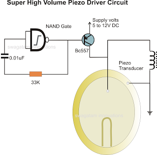
In the previous post, a piezo transducer element was discussed, along with its application in electronic circuits. This article will explore how a piezo transducer can be driven or operated using a simple circuit. The amplification method differs from...
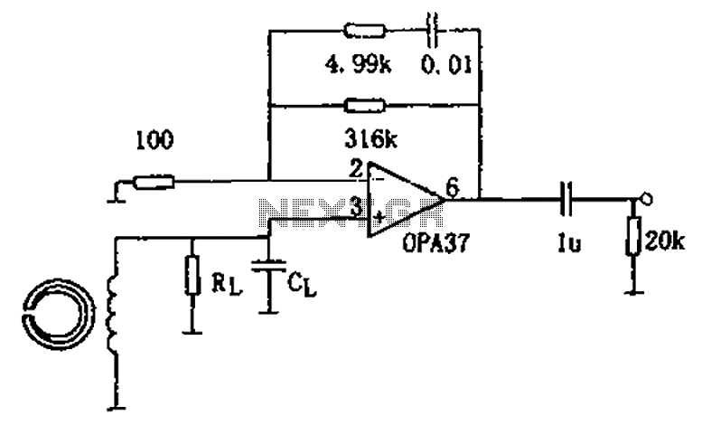
The circuit is a 90s common recorder head amplifier circuit that utilizes the ultra-low noise precision operational amplifier OPA37 as a preamplifier. This circuit is capable of providing standard NAB equalization. At a frequency of 1 kHz, it achieves...
This AC motor speed controller can handle most universal type (brushed) AC motors and other loads up to about 250W. It works in much the same way as a light dimmer circuit; by chopping part of the AC waveform...
This circuit-based project demonstrates the operation of a 555 timer in astable mode to generate pulses with a time period of 0.5 seconds. These pulses can be utilized in various applications, such as blinking an LED or creating decorative...