
2 Watt FM Transmitter

The described circuit functions as a radio frequency oscillator, specifically designed to operate at approximately 100 MHz. The initial stage involves an electret microphone, which serves to capture audio signals from the environment. The microphone's output is a weak analog signal, which is then amplified using a transistor-based audio amplifier. This amplification is crucial for ensuring that the subsequent stages of the circuit can effectively process the audio input.
The first transistor in the audio amplifier stage is responsible for boosting the audio signal's amplitude. The output from the collector of this transistor is crucial, as it serves as the input to the base of the second transistor (T2). The second transistor plays a pivotal role in modulating the RF signal. By applying the amplified audio signal to the base, the resonant frequency of the tank circuit is influenced.
The tank circuit itself comprises an inductor (L1 coil) and a variable capacitor (trim capacitor). This configuration is typical of a Hartley oscillator, which is known for its ability to generate stable oscillations at a specific frequency. The modulation of the resonant frequency occurs through the adjustment of the junction capacitance of the transistor T2. This capacitance is not a fixed value; rather, it is influenced by the voltage at the base of T2. As the audio signal varies, it alters the potential difference across the base-emitter junction, thereby changing the junction capacitance. This dynamic adjustment allows the circuit to effectively superimpose the audio signal onto the RF carrier wave generated by the tank circuit.
In summary, this circuit exemplifies a fundamental approach to RF signal modulation, utilizing a combination of audio amplification and frequency modulation techniques within a Hartley oscillator framework. The integration of the electret microphone, transistor amplifiers, and tank circuit components illustrates a practical application of electronic principles in RF communication systems.The circuit is basically a radio frequency (RF) oscillator that operates around 100 MHz. Audio picked up and amplified by the electret microphone is fed into the audio amplifier stage built around the first transistor. Output from the collector is fed into the base of the second transistor where it modulates the resonant frequency of the tank circ
uit (L1 coil and the trimcap) by varying the junction capacitance of the transistor. Junction capacitance is a function of the potential difference applied to the base of the transistor T2. The tank circuit is connected in a Hartley oscillator circuit. 🔗 External reference
Related Circuits
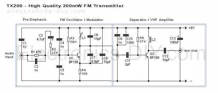
Here is the latest and greatly improved TX200 VFO/VCO FM transmitter. The most versatile transmitter to date that can be turned into high fidelity stereo PLL based 200mW FM transmitter. It is a perfect circuit for transmitting your music...
The game was originally designed to position three balls locked in holes on a slowly rotating ring around the Deadworld. Once the third ball was secured, a mechanical arm would release them, dropping the balls onto the playfield. This...
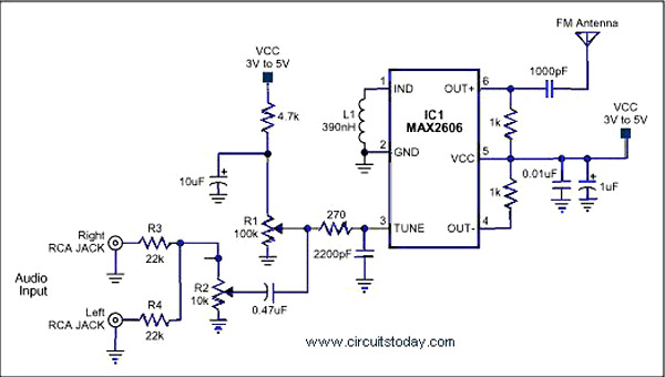
A simple single-chip FM transmitter circuit with a diagram and schematic using the IC MAX 2606, which is a high-performance voltage-controlled oscillator (VCO). The FM transmitter circuit utilizing the MAX 2606 is designed for efficient frequency modulation of audio signals....
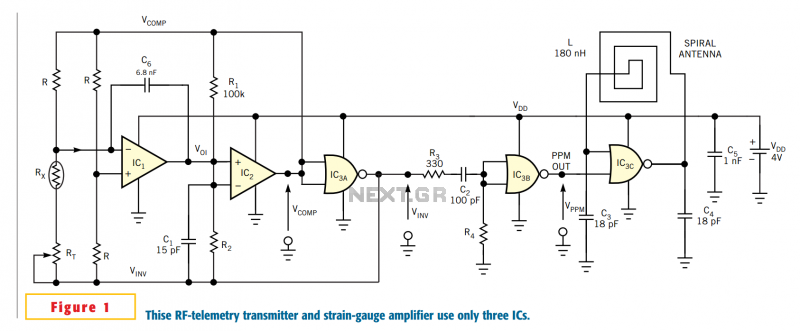
The circuit in Figure 1 meets these criteria and uses only three off-the-shelf ICs and a few passive components. Although dedicated to conditioning the low-level signal a strain-gauge bridge produces, the circuit can operate with almost any resistive transducer...
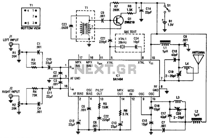
In this application, a BA1404 is utilized to generate an FM MPX baseband signal. This signal modulates a crystal oscillator (Q3) through a dual varactor series modulator. This transmitter can be used to play CD audio on an existing...

This design circuit is for a simple 27MHz transmitter that produces a carrier signal. The circuit generates an unmodulated 27MHz signal, which can be received by a compatible receiver. The transmitter operates as a basic crystal oscillator, with the...