
Single chip FM transmitter circuit using IC MAX 2606

The FM transmitter circuit utilizing the MAX 2606 is designed for efficient frequency modulation of audio signals. The MAX 2606 is a versatile integrated circuit that functions as a voltage-controlled oscillator, allowing for precise control over the output frequency based on the input voltage. This characteristic makes it suitable for applications requiring stable frequency generation.
In the schematic, the circuit typically includes the following key components: the MAX 2606 IC, a power supply, audio input, and an antenna. The power supply provides the necessary voltage for the operation of the circuit, while the audio input can be connected to various audio sources such as microphones or audio players. The output from the MAX 2606 is fed to an antenna, which broadcasts the modulated signal over a designated frequency range.
To ensure optimal performance, it is essential to properly configure the external components connected to the MAX 2606. These components may include resistors and capacitors that determine the modulation index and frequency stability. Additionally, careful consideration must be given to the layout of the circuit to minimize interference and enhance signal quality.
Overall, this FM transmitter circuit is an effective solution for short-range audio broadcasting, offering simplicity in design and functionality.A simple Single chip FM transmitter circuit with diagram and schematic using IC MAX 2606, which is a high performance Voltage controlled oscillator or VCO.. 🔗 External reference
Related Circuits
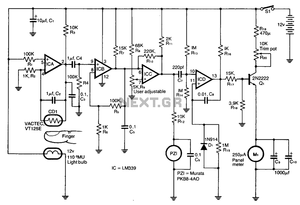
A cadmium sulfide photoresistor (CD1) fingertip can be detected through the filter. CD1 forms part of the sense amplifier feedback network. A section of the sense amplifier (ICA) produces weak signals that may be further amplified by ICB. These...
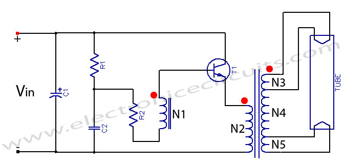
Fluorescent tube light circuit of an inverter that uses a single transistor and a single transformer. This type of inverter can be made in various configurations. The fluorescent tube light circuit described utilizes a basic inverter design that incorporates a...
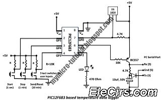
A data logger is a device that records measurements over time. The measurements could be any physical variable like temperature, pressure, voltage, humidity, etc. This project describes how to build a mini logger that records surrounding temperature. A data logger...
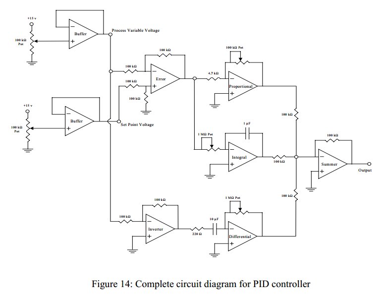
Convert a feedforward operational amplifier PID loop to C code. Assistance is needed for this conversion, as the process is unfamiliar. Input values can be obtained through an ADC, such as voltage or current, but coding a feedforward PID...
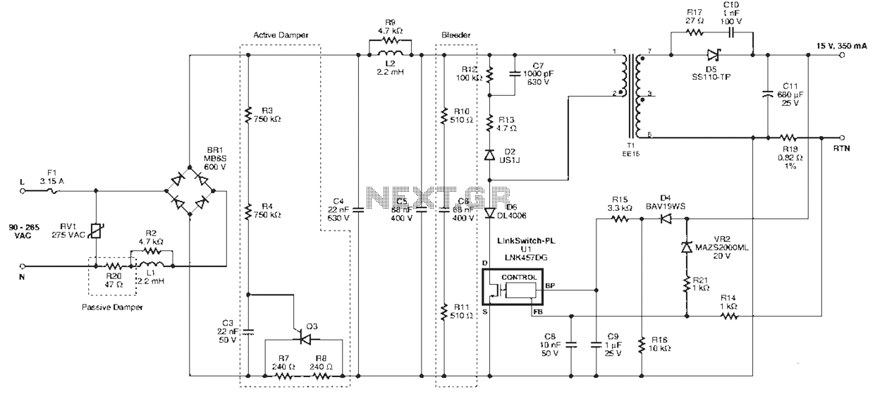
Power Integrations' DER322 reference design employs the LinkSwitch-PL family of LNK460VG devices. This design represents the industry's first alternative 100W A19 incandescent LED driver utilizing a single-layer PCB. It is characterized by low cost, minimal component count, and compact...
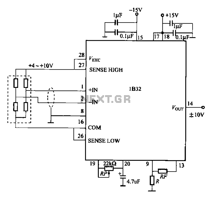
The circuit for bridge measurements is straightforward, as illustrated in the figure. The sensor bridge drive voltage can be adjusted between +4V and +10V, depending on the specific requirements of the sensor. Two fixed gain options of 333.3 and...