
RF-telemetry transmitter features minimal parts count

The described circuit employs a voltage-to-frequency converter (VFC) that effectively transforms the small voltage changes from the Wheatstone bridge into a frequency-modulated signal suitable for further processing. The primary function of the Wheatstone bridge is to measure resistance changes, which correspond to the strain experienced by the gauge. In this configuration, the bridge is balanced under normal conditions, and any strain-induced resistance variation results in an unbalanced condition, causing a measurable voltage difference.
The VFC is crucial for converting this voltage signal into a frequency signal, which is less susceptible to noise and can be easily transmitted wirelessly. The integration process is handled by the operational amplifier configured as an integrator, which continuously ramps the output voltage based on the input current derived from the bridge circuit. This output is then fed into a Schmitt trigger comparator, which generates square wave outputs that toggle between high and low states, effectively creating a square wave signal responsive to the input conditions.
The use of a monostable circuit following the inverter allows for the generation of precise pulse-width modulation (PWM) signals, which can be utilized for controlling the RF transmitter. The timing components R4 and C2 define the pulse width, ensuring that the output pulse is consistently 15 microseconds long, which is critical for maintaining the integrity of the transmitted signal. Additionally, the current-limiting resistor R3 is an essential safeguard against potential latch-up conditions within the integrated circuits, ensuring reliable operation.
Overall, this circuit illustrates a robust method for conditioning low-level signals from resistive transducers and converting them into a form suitable for wireless transmission, making it applicable in various sensing and monitoring applications.The circuit in Figure 1 meets these criteria and uses only three off-the-shelf ICs and a few passive components. Although dedicated to conditioning the low-level signal a strain-gauge bridge produces, the circuit can operate with almost any resistive transducer based on a Wheatstone bridge.
The circuit comprises a VFC (voltage-to-frequency converter) that produces a PPM (pulse-position-modulation) output, and an OOK (on/off-keyed) RF transmitter.
To understand the circuit's operation, assume that the comparator's output is high and, consequently, the inverter's output is low. Also assume that the series combination of the strain gauge, RX, and the trimmer, RT, is always equivalent to R(1+X)>R.
That is, for linear operation, the sensor's resistance variation represents a small fraction of the arm resistance. Under these conditions, the noninverting input of IC1 biases to VDD/2, and the Wheatstone bridge's active arm drives a positive current, II, into the summing node of IC1.
This current causes the integrator's output, VOI, to ramp down toward the low threshold voltage, VTL, of the Schmitt trigger. When VOI=VTL, the comparator's output goes to zero, and the inverter's output consequently rises to VDD.
This action inverts the direction of the integrator's input current, causing the integrator's output to ramp upward to the Schmitt trigger's high threshold voltage. Finally, when VOI=VTH, the comparator's output goes high, and the above sequence repeats indefinitely, producing a free-running oscillation in which the integrator's output ramps up and down between the threshold voltages of the Schmitt trigger (Trace 1 in Figure 2).
Meanwhile, the comparator's output and the inverter's output deliver two square waves with a 50%-duty-cycle ratio (traces 2 and 3, respectively, in Figure 2) that drive the bridge. To produce the PPM signal (Trace 4 in Figure 2), the inverter's output drives a monostable circuit comprising a second inverter, IC3B, and timing components R4 and C2, which produces a 15-µsec-wide pulse.
Current-limiting resistor R3 prevents latch-up of IC3, and R2 and C4 set the output-pulse width.
Related Circuits
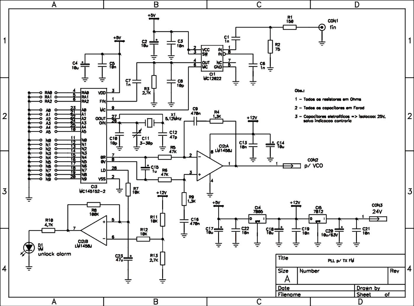
This is a schematic of a synthesized Phase-Locked Loop (PLL) for a low-power FM transmitter. It can also be utilized with other circuits, provided that the loop filter response, components, VCO tank circuit, and appropriate thumbswitch programming keys and...
The transmitter operates within the VHF and VLF frequency ranges on TV channels, though it has not been tested for UHF frequencies. The modulated sound signal spans 5.5 to 6 MHz, which can be adjusted by tuning capacitor C5....
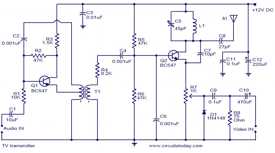
A simple two-transistor TV transmitter circuit that operates from 12V. It is compatible with PAL B and PAL G systems. The described circuit utilizes two transistors to create a basic television transmission system capable of operating on a 12V power...
This circuit utilizes a sawtooth oscillator along with an output amplifier that drives a transistor. The components C1, C2, and L1 are essential for the oscillator's operation, forming a tank circuit that must be tuned to the resonant frequency....
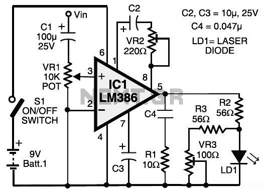
This circuit diagram represents a laser communication system that transmits sound or music signals using a laser beam. The intensity of the laser beam varies in accordance with the amplitude of the sound signal. The variation in the intensity...
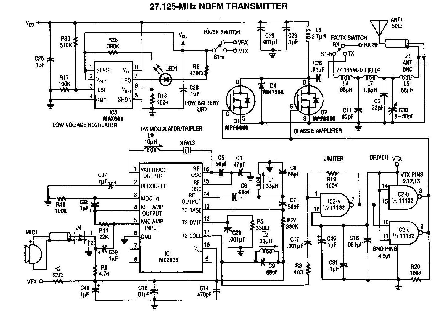
A 27MHz transmitter circuit schematic utilizing the MC2833 and two FET transistors, MPF6660. This design incorporates a Motorola MC2833 one-chip FM transmitter along with several supporting components. The 27MHz transmitter circuit is designed to operate within the FM radio frequency...