
2 watt fm transmitter

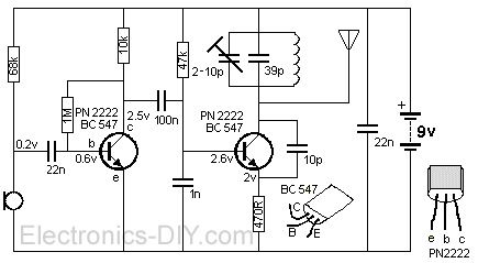
The described RF oscillator circuit operates at approximately 100 MHz, utilizing a configuration that incorporates an electret microphone for audio signal input. The microphone serves as the initial stage of audio signal acquisition, where it converts sound waves into electrical signals. These signals are then amplified by the first transistor, which functions as an audio amplifier. The amplified output from the collector of this first transistor is crucial, as it is used to drive the base of the second transistor.
The second transistor plays a pivotal role in modulating the resonant frequency of the tank circuit, which consists of an inductor (L1 coil) and a variable capacitor (trimcap). This modulation occurs through the control of the junction capacitance of the second transistor, which is a variable parameter influenced by the voltage applied to its base. By adjusting the base voltage, the junction capacitance can be varied, thereby affecting the overall resonant frequency of the tank circuit.
The Hartley oscillator configuration is characterized by its ability to generate oscillations at radio frequencies. In this setup, the tank circuit, which includes the inductor and capacitor, is responsible for determining the frequency of oscillation. The feedback loop established through the transistors ensures sustained oscillation, allowing for the effective transmission of the modulated RF signal. This circuit design is particularly useful in applications such as wireless audio transmission, where the audio signal needs to be transmitted over a radio frequency carrier wave. The overall design emphasizes efficient signal amplification and modulation, making it suitable for various RF communication applications.The circuit is basically a radio frequency (RF) oscillator that operates around 100 MHz. Audio picked up and amplified by the electret microphone is fed into the audio amplifier stage built around the first transistor. Output from the collector is fed into the base of the second transistor where it modulates the resonant frequency of the tank circ
uit (L1 coil and the trimcap) by varying the junction capacitance of the transistor. Junction capacitance is a function of the potential difference applied to the base of the transistor T2. The tank circuit is connected in a Hartley oscillator circuit. 🔗 External reference
Related Circuits
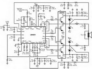
The following circuit illustrates the LM4652 integrated circuit used in a 170 Watt power amplifier configuration. It is commonly utilized in portable HiFi systems. The LM4652 is a high-performance audio amplifier IC designed to deliver substantial power output while maintaining...
This circuit is a diagram of a mini amplifier. The amplifier circuit has a power output of 10 watts and is well-suited for car audio applications. It utilizes the TDA2009A integrated circuit as the power amplifier. To prevent excessive...
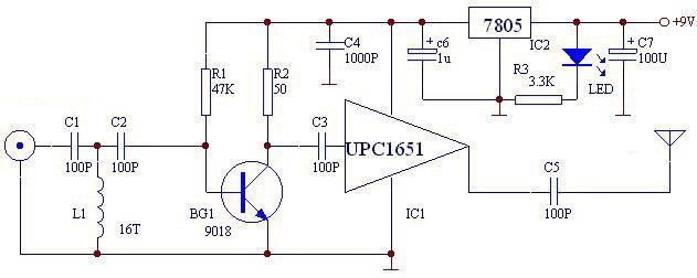
The UPC1651 FM monolithic circuit can be utilized to design a simple, low-cost FM transmitter electronic project. This circuit is specifically designed as a wideband amplifier that covers the HF band through the UHF band. Audio signals from the...
This is a convenient and straightforward general-purpose 50-watt amplifier. The amplifier features an input for connecting devices such as radios, TVs, or stereo equipment. Additionally, it includes a phono input suitable for connecting record players, guitars, microphones, or other...
A simple FM transmitter utilizing a single transistor. Mini FM transmitters are commonly regarded as one of the fundamental circuit types for beginners in amateur electronics. When constructed correctly, they offer clear wireless sound transmission via a standard FM...
The FM transmitter is a simple and compact device with a transmission range of 100-150 meters, offering good sensitivity and low current consumption. The schematic of the transmitter includes a bass amplifier for the first transistor and a frequency...