
10 Watt Stereo Amplifier Circuit Using TDA2009A

The mini amplifier circuit described operates at a power output of 10 watts, making it an efficient choice for car audio systems where space and power conservation are critical. The TDA2009A is a versatile integrated circuit known for its robustness and reliability in audio amplification applications. It is capable of driving speakers directly, making it ideal for automotive environments.
In the schematic, the TDA2009A is typically connected to a power supply that provides the necessary voltage, often in the range of 12V to 14.4V, which is standard for automotive electrical systems. The circuit may include input capacitors for signal coupling, resistors for gain adjustment, and feedback components to stabilize the amplifier's performance.
To manage heat dissipation effectively, a heat sink is employed, attached to the TDA2009A to ensure that the IC operates within safe temperature limits. The use of a thermal compound between the IC and the heat sink enhances thermal conductivity, allowing for efficient heat transfer and preventing thermal overload that could lead to circuit failure.
Additional features may include a low-pass filter at the output to reduce high-frequency noise, ensuring a cleaner audio signal. The circuit may also incorporate protection mechanisms such as fuses or thermal shutdown features to safeguard against short circuits or excessive current draw.
Overall, this mini amplifier circuit is designed for simplicity and effectiveness, making it an excellent choice for enhancing audio quality in automotive applications. Proper layout and component selection are crucial for achieving optimal performance and reliability.This circuit is a circuit diagram mini amplifer. This amplifier circuit has a power of 10 watts. This amplifier circuit is very suitable to apply to your car audio. This amplifier using IC TDA2009A, as amplifeir power. To avoid excessive heat in the IC using some heat sink compound between the heat sink . 🔗 External reference
Related Circuits
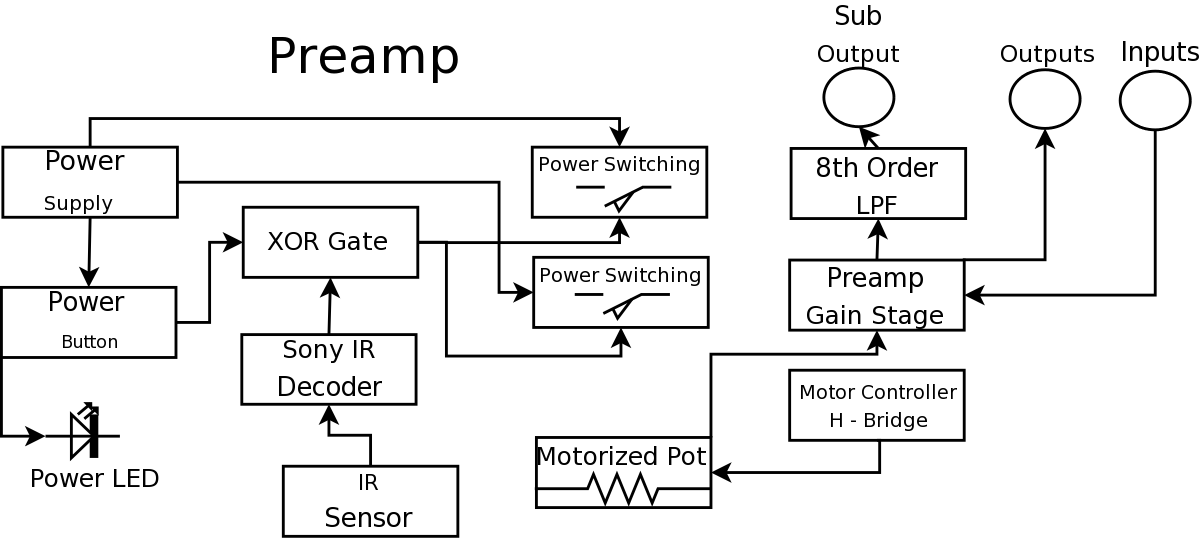
During a Digital Projects Lab, the professor suggested incorporating more circuit-level work into a project. To achieve this, a preamplifier was designed, which included an infrared (IR) remote control to replace a previously built version. The earlier preamplifier functioned...
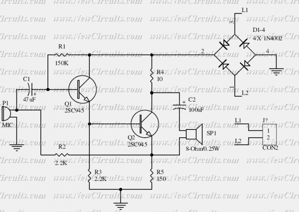
This is the basis of electronics telephone sets. You can use it to replace the talking circuit of an old telephone set with new design, better noise rejection and reliability one. Also you can use it to build a...
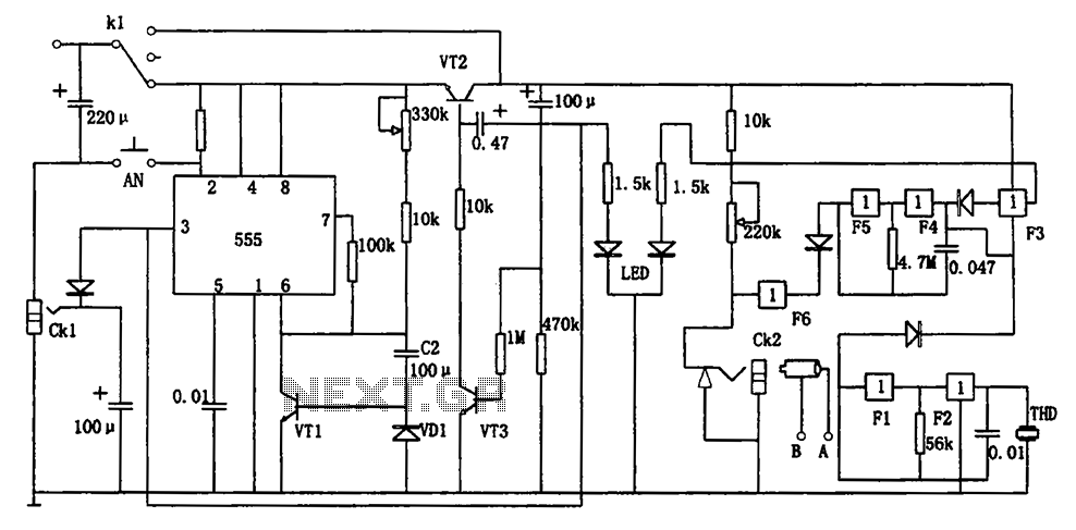
The circuit represents a general multi-function alarm and timing mechanism. Its timing capabilities range from 5 minutes to 3 hours. The timing components include C2, VD1, and VT1. The circuit utilizes a capacitance multiplier with a 555 timer. CK1,...
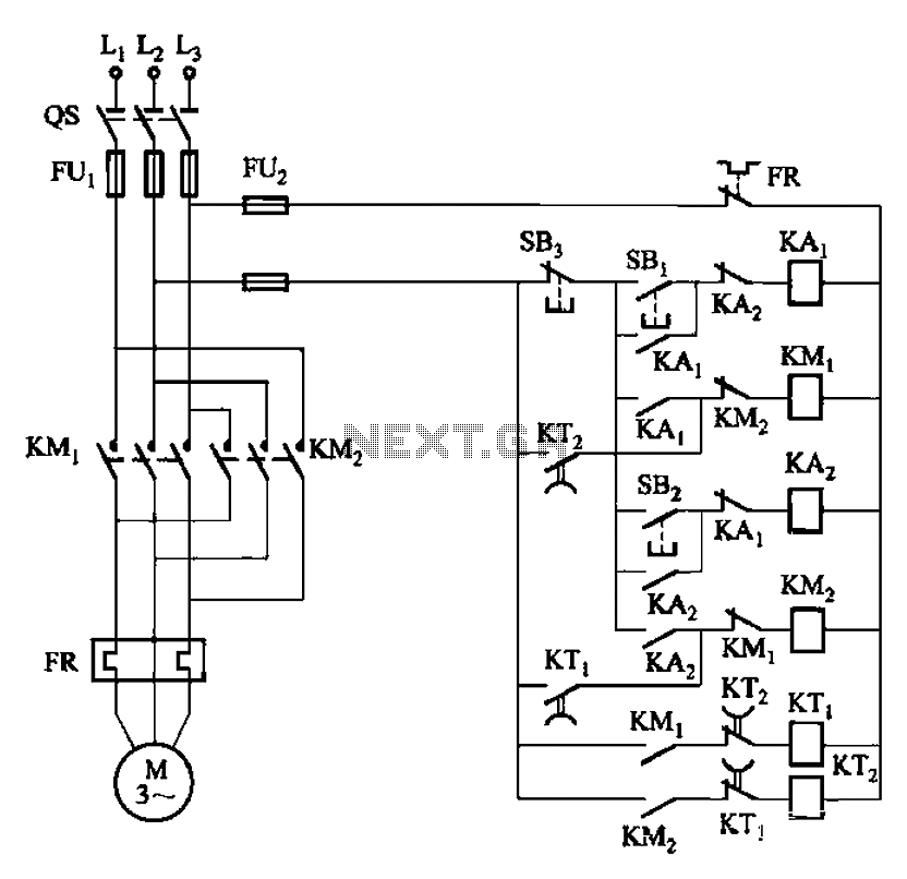
The circuit depicted in Figure 3-131 utilizes a relay instead of a speed control relay. It is designed to operate effectively in dusty environments and other challenging conditions. The circuit operates by employing a relay as a primary switching mechanism,...
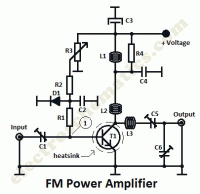
This is a 1 watt FM amplifier with a robust design that can be used to amplify an RF signal in the 88 to 108 MHz band. It is highly sensitive when utilizing quality RF power amplifier transistors, trimmers,...
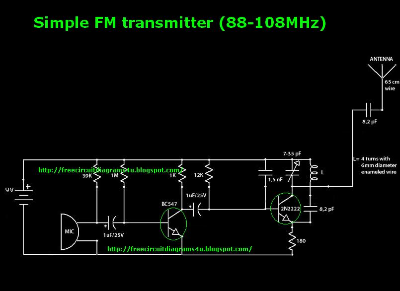
This is a simple transmitter circuit diagram that offers decent coverage. The circuit can operate with a power supply of 9-12V. To tune this circuit... This simple transmitter circuit is designed to provide reliable performance within the specified voltage range....