
20 minute lamp fader

This circuit utilizes a bridge rectifier to convert 120VAC to a DC voltage suitable for driving a 60-watt lamp via a MOSFET. The selected bridge rectifier must be rated for at least 200 volts and 5 amps to ensure safe operation. The circuit employs an LM324 operational amplifier, which generates a 700 Hz triangle waveform. This waveform is used to control the brightness of the lamp by adjusting the duty cycle of a rectangular waveform produced at pin 14, based on the comparison of signals at pins 12 and 13.
The brightness ramp-up of the lamp is adjustable through a 270K resistor connected to pin 9 of the LM324. This allows for a customizable illumination duration, with the default being approximately 20 minutes. A 6.2K, 5-watt resistor and a zener diode are included to regulate the circuit's power supply voltage down to 12 volts DC. The circuit incorporates a 3300uF capacitor, which is charged during operation and discharged via a diode and a 10K resistor when power is removed, ensuring that the circuit can be safely reset after use.
To minimize radio frequency interference (RFI), a 2.2-ohm resistor in series with a 0.015uF capacitor is connected across the lamp. This configuration helps to filter out any unwanted noise generated during operation. The circuit is designed with safety in mind, as it is directly connected to the AC line. Proper precautions should be taken to avoid any electrical hazards. Testing and troubleshooting should be conducted with the power off and by using a 9-volt battery across the zener diode for preliminary checks. When the circuit is functioning correctly, the DC voltages at various pins of the LM324 should measure around 4.3 volts. If all checks are satisfactory, a variac can be used to gradually apply the full line voltage for operational verification.In this circuit, a 120VAC lamp is slowly illuminated over a approximate 20 minute period. The bridge rectifier supplies 120 DC to the MOSFET and 60 watt lamp. A 6.2K, 5 watt resistor and zener diode is used to drop the voltage to 12 volts DC for the circuit power. The bridge rectifier should be rated at 200 volts and 5 amps or more. In operation, a 700 Hz triangle waveform is generated at pin 1 of the LM324 and a slow rising voltage is obtained at pin 8.
These two signals are compared at pins 12 and 13 to produce a varying duty cycle rectangular waveform at pin 14, which controls the MOSFET and brightness of the 60 watt lamp. When power is applied, the lamp will start to illuminate within a minute or so, and will slowly brighten to full intensity in about 20 minutes. You can make that longer or shorter with adjustments to the 270K resistor at pin 9. The 2.2 ohm resistor and .015uF cap connected to the lamp serve to supress RFI. The diode at pin 9 and 10K resistor on pin 8 are used to discharge the 3300uF cap when power is removed.
Power should be off for a few minutes before re-starting. Caution: This circuit is connected directly to the AC line and presents a hazard if any part is touched while connected to the line. Use caution and do not touch any parts while the circuit is connected to the AC line. You may want to use a 9 volt battery connected across the 12 volt zener to check the basic operation.
The DC voltage at pins 1,2,3,5,6,7 will all be around 4.3 volts if the circuit is working correctly. If the DC voltages are all correct, you can use a variac to slowly apply the full line voltage and check for proper operation. 🔗 External reference
Related Circuits
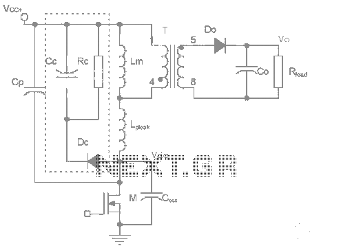
The work process analysis circuit diagram illustrates the use of a flyback converter transformer model. The flyback transformer primarily consists of ideal transformer magnetizing inductance and leakage inductance components. The flyback converter circuit exhibits high-frequency resonance at both ends...
The Implantable Lamp (A3024) is a radio-controlled lamp powered by a battery. Once encapsulated in epoxy and silicone, it is waterproof and compact, allowing it to be implanted in an animal. The A3024 can theoretically be activated by any...
The UBA2021 can be utilized as a 600 V lamp controller and half-bridge driver integrated circuit (IC) for high-power applications. It is designed for long-life compact fluorescent lamp (CFL) and tubular fluorescent lamp (TL) applications. The UBA2021 is a versatile...
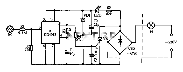
Diodes VD2 to VD5 and SCR form the main circuit of a touch switch. Resistor R5 and diode VD1 create a power supply circuit that outputs approximately 12V DC, which is utilized for a manifold A application. The circuit...
It is very convenient to automatically light a lamp in our absence during the evening when it gets dark. This automatic night lamp circuit can be utilized to illuminate staircase lights, porch lights, etc., automatically using a domestic power...
This circuit resembles the "Fading Red Eyes" circuit found in the LED section, designed to fade a pair of red LEDs. In this iteration, the lamps are dimmed by adjusting the duty cycle, allowing for the use of higher...