
Automatic Night Lamp Circuit PCB

The automatic night lamp circuit is designed to provide illumination in areas such as staircases and porches without the need for manual intervention. The circuit primarily consists of a Light Dependent Resistor (LDR), a Silicon Controlled Rectifier (SCR), and a few passive components, allowing it to operate efficiently with a standard domestic power supply.
The LDR serves as the primary sensor in this circuit. It is a type of resistor whose resistance decreases with increasing incident light intensity. During the day, when ambient light levels are high, the resistance of the LDR is low, which prevents the SCR from being triggered. As the sun sets and the light levels drop, the resistance of the LDR increases significantly. This change in resistance creates a voltage drop across the LDR, which can be utilized to provide the necessary gate trigger voltage to the SCR.
The SCR acts as a switch that can be turned on with a small gate current. When darkness is detected by the LDR, the voltage across the SCR's gate-cathode terminals reaches a threshold level, allowing current to flow through the SCR and effectively closing the circuit. This action activates the connected lamp, providing the desired illumination.
To adapt the circuit for use with a compact fluorescent lamp (CFL), modifications may be required, such as adjusting the current limiting resistors to accommodate the different electrical characteristics of the CFL compared to a traditional filament lamp.
Overall, this automatic night lamp circuit is a practical solution for enhancing safety and convenience in residential settings, ensuring that essential areas are illuminated during the night without requiring manual operation. The simplicity and cost-effectiveness of the design make it an attractive option for homeowners seeking an automated lighting solution.It is very convenient to light a lamp in our absense in the eving when it gets dark. This automatic night lamp circuit can be used to light staircase light, porch light etc automatically using domestic powersupply. It is very in expensive in construction and we dont have to employ or depend anybody to put on the lights when we are out of station.
We can connect a CFL in place of filament lamp by making necessary alterations to the circuit. An SCR and LDR together plays the role of automation in this circuit. In figure, the resistance of LDR is low during daytime and high during night. So the required trigger pulse is developed across the SCR when it becomes dark and it is applied acrosss the gate cathod terminals and SCR is triggered and the circuit is closed. 🔗 External reference
Related Circuits
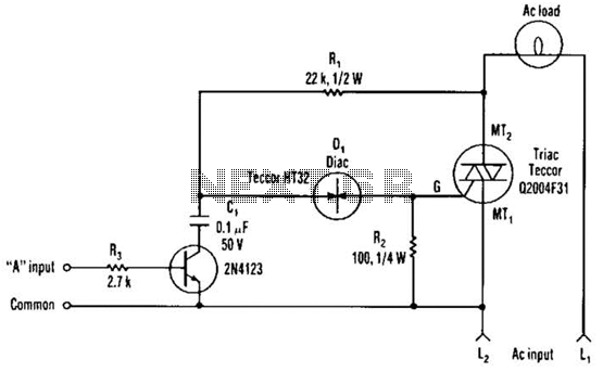
The single transistor connected between the capacitor and the common side of the AC line allows a logic-level signal to control this TRIAC power circuit. Resistor R2 prevents false triggering of the TRIAC by the trickle current through the...

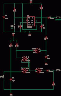
The circuit diagram illustrates a group of four analog electronic circuit switches (S1 to S4). Switches S1, S2, and S3 are utilized in a parallel delay circuit. When the power is activated, resistor R4 drives the triac VT, which...

The adjustable voltage monitor can be used to check whether the voltage in a circuit remains within a given range. If the DC voltage is less than the voltage at pin 5 of U1-B, then LED1 will light. If...
This circuit is a simple -5V power supply using a 555 timer, designed for low-power analog applications involving FET operational amplifiers. The circuit converts +5V to -5V to create a dual power supply. It operates as a 555 astable...
An LED is usually a series resistor needed to ensure that the LED does not get too much power. The disadvantage of such resistance is that the current through the LED and thus the brightness changes as the voltage...
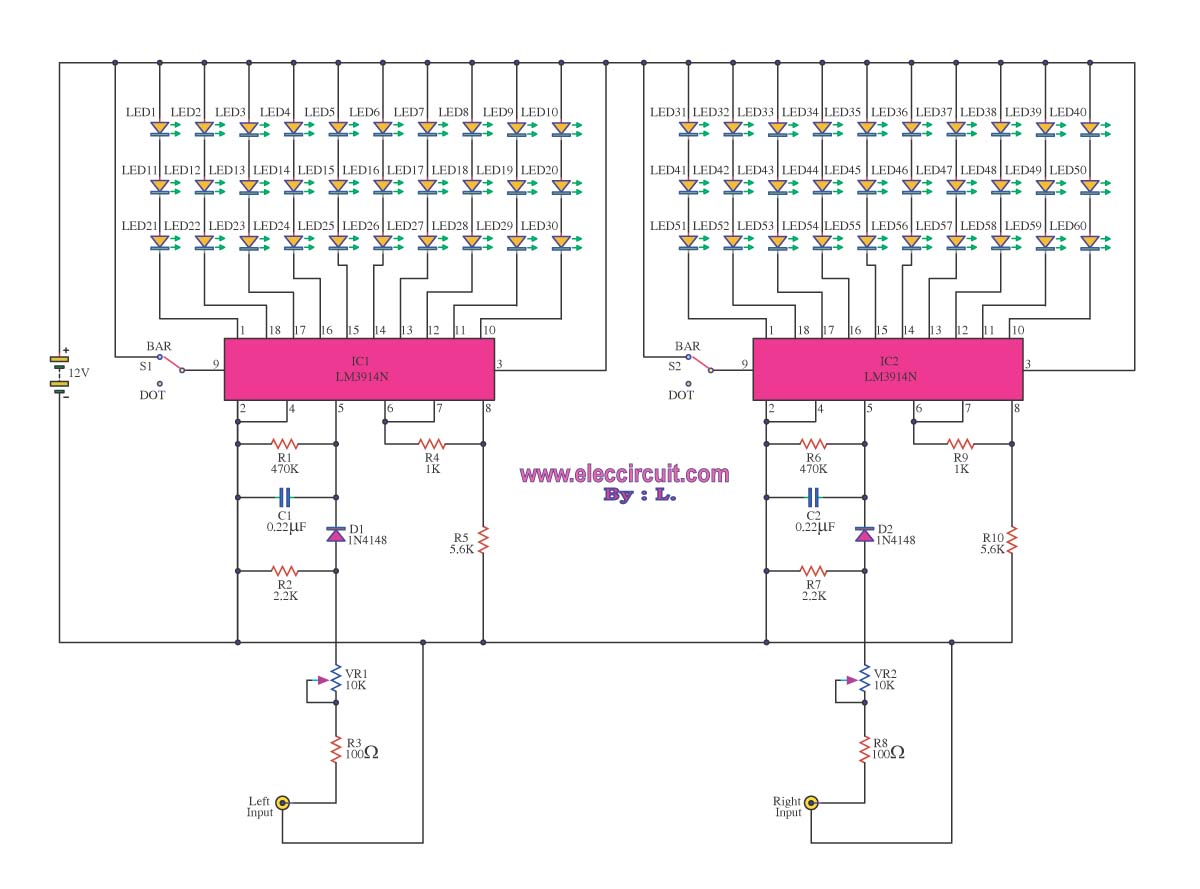
A VU meter is utilized to display the power level of audio signals and also serves as an aesthetic element. When purchasing a VU meter kit from an electronics store, options include assembling various parts independently or selecting a...