
20 Watt audio Amplifier

The capacitors C4 and C5 should preferably be as close to the IC down. More: Parts List
R1 = 1 M ½
R2, R3, R4 = 22 kOhm
R5 = 10 kOhm
R6 = 200 kOhm
R7 = 1 Ω
C1 = 1 uF
C2, C3 = 10 uF
C4 = 100 uF
C5 = 100 nF
C6 = 2200 uF
C7 = 22 nF
IC1 = LM1875
LS1 = 4-8 Ω speaker
The described amplifier circuit utilizes the LM1875 integrated circuit, which is a high-performance audio power amplifier designed to deliver significant output power with minimal distortion. The circuit is capable of producing 20 watts of output power into an 8-ohm load, and it can also achieve up to 30 watts under optimal conditions with a suitable power supply.
The amplifier is powered by a 60V DC supply, which is essential for achieving the desired output levels. The careful selection of resistors and capacitors in the circuit plays a crucial role in defining the performance characteristics of the amplifier. The resistors R1, R2, R3, R4, R5, R6, and R7 are strategically chosen to set the gain and stabilize the amplifier's operation. R1, at 1 MΩ, serves as a feedback resistor, while R2, R3, and R4, each at 22 kΩ, help to define the input impedance and gain structure.
Capacitors C1, C2, C3, C4, C5, C6, and C7 are integral to the amplifier's performance. C1, with a value of 1 µF, is used for coupling, while C2 and C3, both rated at 10 µF, help in bypassing and filtering. C4, a 100 µF capacitor, is critical for power supply decoupling, and C5, with a value of 100 nF, is used for high-frequency noise filtering. C6, at 2200 µF, provides additional power supply smoothing to ensure stable operation under load, and C7, at 22 nF, is used for further high-frequency stability.
The output stage is designed to drive a loudspeaker (LS1) with an impedance range of 4 to 8 ohms, making the amplifier versatile for various audio applications. The placement of capacitors C4 and C5 close to the LM1875 IC is recommended to minimize inductive and resistive losses, enhancing the overall performance of the amplifier.
This amplifier circuit is suitable for various applications, including home audio systems, small public address systems, and other audio amplification needs where compact size and high efficiency are desirable. The design emphasizes reliability and sound quality, making it a popular choice among audio enthusiasts and engineers alike.This is a standard amplifier based on LM 1875. It can deliver 20 W, with an 8 ? speaker and 60V power supply even 30 W. The capacitors C4 and C5 should preferably be as close to the IC down. Parts List R1 = 1 M ½ R2, R3, R4 = 22 kOhm R5 = 10 kOhm R6 = 200 kOhm R7 = 1 ? C1 = 1 uF C2, C3 = 10 uF C4 = 100 uF C5 = 100 nF C6 = 2200 uF C7 = 22 nF IC1 = LM1875 LS1 = 4-8 ? speaker 🔗 External reference
Related Circuits
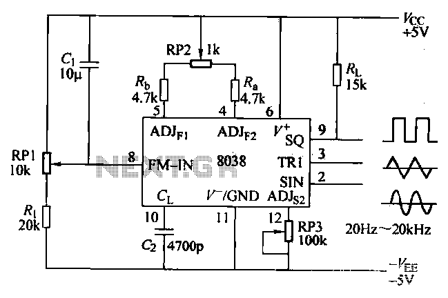
The ICL8038 function generator is an audio composition device that utilizes the ICL8038 integrated circuit. The resistance Ri potentiometer RP1 is used to determine the flow potential. Typically, the output is set to approximately 2Vcc / 3. Lowering the...
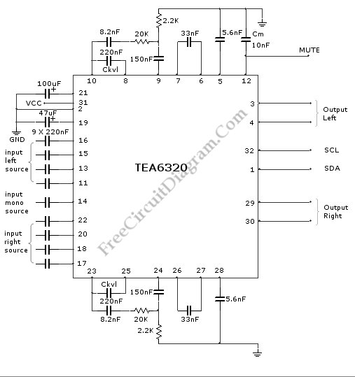
High-end audio equipment is typically controlled digitally by a microprocessor (microcontroller) system. It is necessary to have a digital interface that allows for effective communication and control. High-end audio systems utilize a microcontroller to manage various functionalities, enabling precise control...

Ensure that the 12V (yellow) wire is connected to the right side of the D-connector (viewed from behind, with the connector holes facing away and the curved portion of the connector oriented upwards). The D-connector, commonly utilized in various electronic...
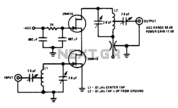
This 200 MHz JFET cascode circuit features low cross-modulation, large signal handling ability, no neutralization, and automatic gain control (AGC) managed by biasing the upper cascode JFET. The only special requirement of this circuit is that the drain-source saturation...
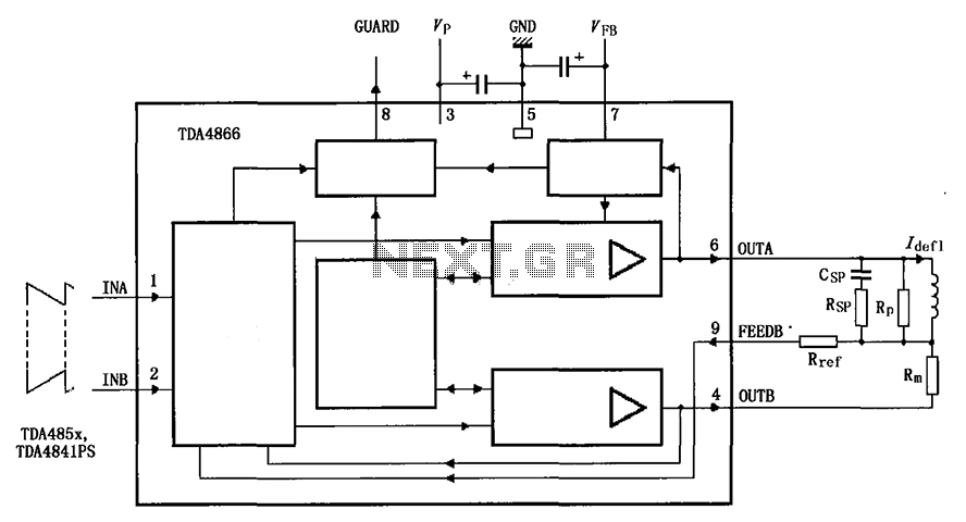
The TDA4866 is a 90-color power amplifier designed for vertical deflection systems, operating at a frequency range of 50 to 160 Hz. The CRMM circuit is implemented to ensure a high current drive input. The amplifier features a dual...
The circuit is designed for driving small UHF TV transmitters, providing a gain of 7 dB and capable of amplifying signals within the frequency range of 470-860 MHz. Key components include resistors, capacitors, and transistors. This circuit serves as a...