
20 Watt Power Amplifier

The 20 Watt car power amplifier circuit utilizing the TDA 2005 is designed to enhance audio performance in automotive environments. The TDA 2005 IC is engineered for high-efficiency audio amplification, making it suitable for car audio systems where space and power efficiency are critical. This integrated circuit features built-in protection mechanisms, including short circuit and thermal overload protection, which safeguard the amplifier during operation.
The bridge configuration employed in this circuit allows for effective power delivery, maximizing the output to 20 watts when connected to 2-ohm speakers. This configuration is essential for achieving higher power levels without requiring additional components, simplifying the overall design while ensuring robust performance.
The additional circuit based on the TDA1553 further complements the audio amplification capabilities, functioning as a Class-B audio amplifier. The simplicity of this circuit, comprising primarily the IC and a capacitor, minimizes the complexity of the design, making it accessible for various applications in car audio systems.
In terms of connections, the input (IN) of the amplifier is linked to the output of the audio receiver, ensuring that the signal is properly amplified before reaching the output stage. The output (Uoutput) is then connected directly to the speaker. It is vital to maintain proper isolation between the speaker and the chassis ground to prevent potential damage to the TDA2004 integrated circuit. This precautionary measure is critical in ensuring the longevity and reliability of the amplifier circuit in automotive applications.20 Watt Car Power Amplifier circuit diagram bases TDA 2005. This TDA 2005 IC was designed specifically in car audio system for power boosting applications. This IC has a protection against short circuit and overheating. In the above circuit use a bridge configuration that will deliver 20W of output power with 2 ohm speakers. The scheme given here is a car stereo amplifier circuit can be used in That car or other vehicle. The circuit is based TDA1553, which is a Class-B audio amplifier. As you can see this circuit is very simple, consisting only of theICand thecapacitor6. Here is a circuit diagram of car stereo. This 20w car audio amplifier circuit described here offers a 20watt booster that will allow you to realize the power amplifier with which one can increase the power output from the carstereoup to20Wattsmaximum. The inputINis connected to theoutputof thereceiver, Uoutputis connectedto the speakeras shownoncaraudioamplifierscheme.
It is veryimportanttoensurethat thespeakerhas no connection tothe chassis(ground)ifnot, the integrated circuitIC1, aTDA2004will. 🔗 External reference
Related Circuits
Not so much a real project as a field day for experimenters, this article describes the methods you can use to tailor an amplifier to a specific driver. Much is empirical (i.e. design by experiment, trial and error), and...
The LTC3731H is a linear three-phase step-down voltage regulation power control unit from the company, capable of driving N-channel MOSFETs. It operates within a temperature range of up to 140°C and supports a control frequency of up to 600...
These photos were made in the years 1956 and 1957. On photo nr. 3, on the right, at the bottom, is the GMD. The work that was done at the objekt was of course top secret. It was strictly...
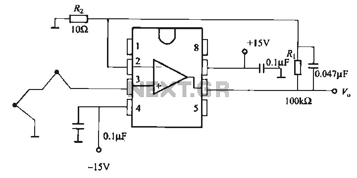
The OP07 is a low drift operational amplifier with a maximum voltage drift of 30 µV/°C and a maximum drift of 0.6 mV/V/°C. It features low noise characteristics with a maximum noise level of 0.6 pV/√Hz, offering ultra-stability with...
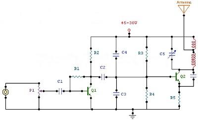
The circuit is a radio frequency (RF) oscillator that operates around 100 MHz. Audio signals captured and amplified by the electret microphone are sent to an audio amplifier stage constructed around the first transistor. The output from the collector...
The primary component of this circuit is the LM386 amplifier chip. It also incorporates a transistor input to buffer the input signal and provide additional gain for the LM386. This compact unit has proven useful in various scenarios, particularly...