
2000 suburban: relay air compressor LT v i manually put power

The compressor relay is a critical component in the operation of a compressor system, typically found in HVAC units or refrigeration systems. Its primary function is to control the power supply to the compressor motor, allowing it to start and stop based on the system's demands. The relay is usually located within the electrical panel or housing that also contains the solenoid valve, which regulates the flow of refrigerant. To locate the relay, it is advisable to refer to the specific service manual for the compressor model in question, as the placement can vary significantly between different manufacturers and models.
Testing the pressure sensor on the compressor assembly can be performed using a multimeter. First, ensure that the compressor is powered off to prevent any electrical hazards. Next, locate the pressure sensor, which is typically mounted on the plastic tank of the compressor. Disconnect the sensor's electrical connector to facilitate testing. Set the multimeter to measure voltage and connect the leads to the corresponding terminals of the sensor. When the compressor operates, the sensor should output a voltage between 0.5 and 4.5 volts, depending on the pressure within the system. If the output voltage is outside this range or non-existent, the pressure sensor may be faulty and require replacement.
For further assistance, online resources and forums may provide valuable insights, as many experts share their knowledge regarding similar issues. These platforms can offer quick responses to inquiries related to compressor systems and their components.Need to know where is the phisical location of the compressor relay. Also do you know how to test the pressure sensor on the plastic tank on the compressor assembly itself Sorry to take so long to get back with you. I have not been able to nail down the exact location of the relay with the information available tome.
One source referenced that the relay was within the housing that contained the solenoid and compressor. This i can not confirm. The pressure sensor gives an output of. 5 to 4. 5 volts. Reference the schematics i sent yesterday. Ask-a-doc Web sites: If you`ve got a quick question, you can try to get an answer from sites that say they have various specialists on hand to give quick answers. Justanswer. com. Traffic on JustAnswer rose 14 percent. and had nearly 400, 000 page views in 30 days. inquiries related to stress, high blood pressure, drinking and heart pain jumped 33 percent. I was having a terrible problem with the wheel bearings on my 98 Chevy Cavalier and I suspect that using this website saved me plenty of time and money.
Todd L Rochester NY I was having a terrible problem with the wheel bearings on my 98 Chevy Cavalier and I suspect that using this website saved me plenty of time and money. Todd L Rochester NY Wonderful service, prompt, efficient, and accurate. Couldn`t have asked for more. I cannot thank you enough for your help. Mary C. Freshfield, Liverpool, UK This expert is wonderful. They truly know what they are talking about, and they actually care about you. They really helped put my nerves at ease. Thank you so much! Alex Los Angeles, CA Thank you for all your help. It is nice to know that this service is here for people like myself, who need answers fast and are not sure who to consult.
GP Hesperia, CA Just let me say that this encounter has been entirely professional and most helpful. I liked that I could ask additional questions and get answered in a very short turn around. Esther Woodstock, NY Thank you so much for taking your time and knowledge to support my concerns. Not only did you answer my questions, you even took it a step further with replying with more pertinent information I needed to know. Robin Elkton, Maryland 🔗 External reference
Related Circuits
This circuit is a simple form of the commercial UPS, the circuit provides a constant regulated 5 Volt output and an unregulated 12 Volt supply. In the event of electrical supply line failure the battery takes over, with no...
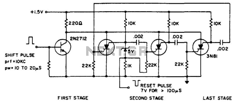
The ring counter operates from 1.0 to 6.0 V and requires only 6 mW at 1.5 V. The reset pulse activates the first stage with its trailing edge. The maximum shift pulse width increases with voltage and approaches 70...
Most devices used in amplifier output stages exhibit significant non-linearity, with transistors (both bipolar and FET) being particularly problematic. These components are almost always employed within a global feedback loop to mitigate their non-linear characteristics. Similarly, tetrode and pentode...
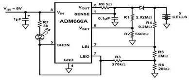
The ADM666A application note provides a detailed explanation of a low-cost battery charger circuit, including maximum output voltage, charge termination voltage calculation, battery voltage level monitoring, and circuit efficiency optimization. The ADM666A utilizes an NPN transistor and a P-channel...
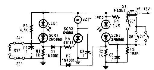
A straightforward high-power alarm driver electronic project can be developed using this circuit diagram. This high-power alarm driver project utilizes a low-power SCR to trigger a high-power SCR. When switches S2, S3, or S4 are opened or switches S5,...
This circuit diagram illustrates a resource replacement for 3V mercury cells or other small batteries. It has various applications, including powering a front panel multi-adapter with a digital thermometer in a computer. The circuit draws power from the PC,...