
scr high power alarm driver circuit design

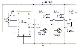
The circuit operates on the principle of semiconductor switching using silicon-controlled rectifiers (SCRs). The initial activation of SCR1 or SCR2 occurs through the manipulation of the designated switches. When S2, S3, or S4 is opened, SCR1 is triggered, while closing S5, S6, or S7 activates SCR2. Both SCRs serve as gate control devices that, once triggered, remain in a conductive state until the power is interrupted or reset.
Diodes D1 and D2 play a crucial role in the circuit by ensuring that the current flows in the correct direction to trigger SCR3. Resistor R5 is used to limit the current flowing through the triggering path, protecting the SCRs from excessive current that could damage them.
The buzzer (BZ1) is an essential component of the alarm system, providing an audible alert when the circuit is activated. The continuous sound of the buzzer serves as a warning signal until the reset switch (S1) is engaged, allowing the user to deactivate the alarm and reset the system.
Power supply considerations are important for the functionality of this circuit. A DC power supply capable of delivering a voltage between 6 and 12 volts is required to ensure proper operation of the SCRs and the buzzer. The choice of power supply voltage may affect the performance of the circuit, particularly the volume of the buzzer.
This alarm driver circuit is suitable for various applications where a high-power alarm is necessary, providing a reliable and effective solution with minimal component requirements.A very simple high power alarm driver electronic project can be designed using this circuit diagram. This high power alarm driver electronic project is based on low power SCR which trigger a high power SCR. When a switch is opening (S2, S3, S4) or closing (S5, S6, S7), either SCR1 or SCR2 triggers. This triggers SCR3 via D1, D2, and R5. When t he alarm is active the BZ1 buzzer will sound continuously, until the S1 reset switch is preset. This electronic circuit require few electronic components and must be powered from a dc power supply circuit, that will provide an output voltage between 6 and 12 volt. 🔗 External reference
Related Circuits

The high-temperature alarm will emit a beep and the LED will blink when the temperature of the device rises abnormally. This simple overheating alarm is designed to monitor heat levels. The high-temperature alarm circuit is an essential safety device used...

This circuit initiated the development of various Link Telephone Intercom designs. Originally created in 1996 using heavy-duty relays and contact banks, it was updated last year by replacing a simpler transistor multivibrator with IC1, substituting all relays and contact...

This AM radio receiver circuit utilizes the TDA1083 radio IC, which is suitable for constructing a simple medium frequency (MF) band radio. The schematic operates within a frequency range of 300 kHz to 3 MHz. The circuit is straightforward...

This small device can be aimed at a television to jam the remote control signal. The circuit design is straightforward. A 555 timer is configured as an astable multivibrator operating at a frequency of approximately 38 kHz, which is...
This is a small circuit designed as an insect repellent, targeting mosquitoes and birds by producing high-frequency audio signals. These signals interfere with the hearing of insects, making it unbearable for them, causing them to flee. The operation of...
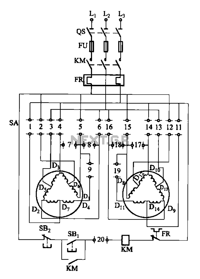
The 3-119 circuit shown in the figure combines switch SA to realize the stator windings, specifically the 2, Y, and 2Y connections, which correspond to the motor speed n1. The 3-119 circuit is designed to facilitate the control of motor...