
22 Watt Audio Amplifier Circuit

The 22-watt amplifier circuit is designed for versatility, making it suitable for various audio applications, including automotive, home theater, and computer audio systems. The compact nature of the design allows for easy integration into existing setups without requiring significant modifications.
The circuit typically employs a power amplifier chip, which is the heart of the amplifier. This chip is responsible for boosting the audio signal to a level that can drive speakers effectively. Given the output power rating of 22 watts, the amplifier is capable of delivering substantial sound levels suitable for most casual listening environments.
To ensure optimal performance, the circuit is designed to operate efficiently, consuming around 60 watts of input power. The power dissipation of approximately 28 watts indicates that a considerable amount of energy is converted into heat during operation. Therefore, the inclusion of a heatsink is crucial. A properly sized heatsink will help dissipate this heat, maintaining the temperature of the amplifier chip within safe operating limits. This not only prevents thermal overload but also enhances the longevity and reliability of the amplifier.
When selecting a heatsink, factors such as thermal resistance, airflow, and mounting options should be considered to achieve effective thermal management. The heatsink should be capable of dissipating heat efficiently to ensure that the amplifier operates reliably without overheating.
In summary, the 22-watt amplifier circuit is a practical and economical solution for enhancing audio systems, with a design that prioritizes compactness and efficiency. The requirement for a heatsink underscores the importance of thermal management in maintaining the performance and durability of the amplifier.The 22 watt amp is easy to build, and very inexpensive. The circuit can be used as a booster in a car audio system, an amp for satellite speakers in a surround sound or home theater system, or as an amp for computer speakers. The circuit is quite compact and uses only about 60 watts. The circuit is not mine, it came from Popular Electronics. 2. T he circuit dissipates roughly 28 watts of heat, so a good heatsink is necessary. The chip should run cool enough to touch with the proper heatsink installed. 🔗 External reference
Related Circuits
Christmas is approaching, and it is the time of year when electronics students and hobbyists consider creating a Christmas circuit for their homes, particularly one that features flashing lights. Numerous circuits and kits are available that can flash various...
An AM radio receiver circuit utilizing an FM IC chip as the primary component. This AM radio receiver circuit incorporates hand-wound coils to adjust the frequency within the AM bandwidth. The AM radio receiver circuit is designed to capture amplitude-modulated...
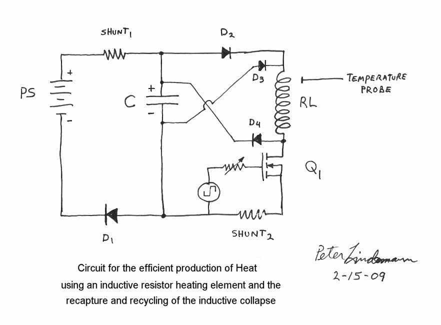
Rosemary's original test circuit is shown in the article she tried to have published in a refereed scientific journal, but the submission was always rejected. In the last 5 months, I have had extensive email correspondence, and numerous telephone...
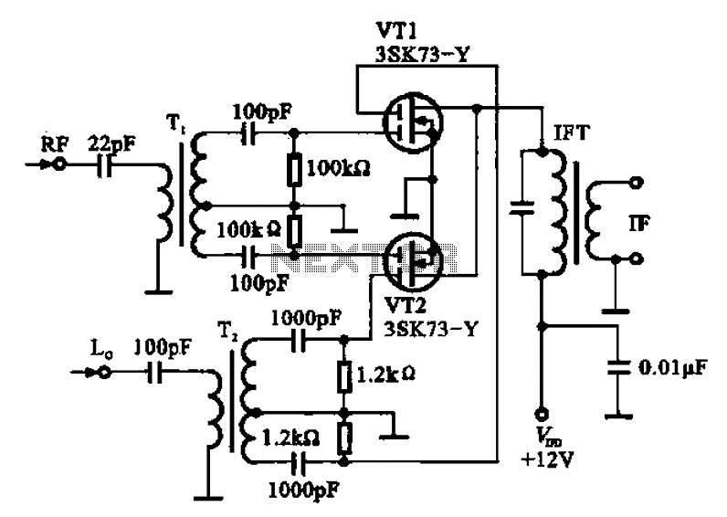
A balanced mixer circuit is illustrated using two dual-gate field effect transistors (FETs). The RF signal is coupled to the gates of these transistors through an input signal transformer (T1). Additionally, a local oscillation signal is introduced to the...
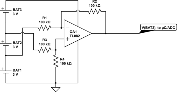
Utilize a high-performance microcontroller (Piccolo TMS320F28035, 12-bit resolution, +/- 4 LSB offset, +/- 60 LSB gain) to measure the voltage across stacked battery cells and control related analog electronics for charge equalization. The microcontroller will also save data in...
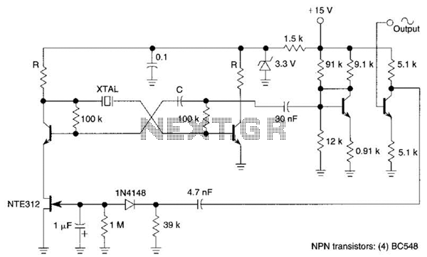
Q1, Q2, and the associated circuitry constitute a modified astable multivibrator where the loop gain is automatically adjusted to the threshold of oscillation by field effect transistor Q3. Q4 amplifies the signal at the collector of Q2 and isolates...