
AM Radio Receiver Circuit

The AM radio receiver circuit is designed to capture amplitude-modulated (AM) signals and convert them into audible sound. The core of this circuit is an FM IC chip, which is typically optimized for frequency modulation but can be adapted to receive AM signals through specific configurations.
The circuit begins with the antenna, which collects the incoming radio waves. The signals are then fed into a front-end amplifier, which enhances the weak signal strength for better processing. Following amplification, the signal enters the FM IC chip, which has been configured to demodulate AM signals. This involves detecting the amplitude variations in the signal, which correspond to the audio information being transmitted.
Hand-wound coils play a crucial role in tuning the circuit to the desired AM frequency. These coils are inductors that, together with capacitors, form a resonant LC circuit. By adjusting the number of turns in the coil and the value of the capacitor, the circuit can be tuned to specific frequencies within the AM bandwidth, typically ranging from 530 kHz to 1700 kHz.
The output from the FM IC chip is an audio signal that is still relatively weak, requiring further amplification. This is achieved through a power amplifier stage, which drives a speaker or an earphone, allowing the audible sound to be heard.
In summary, this AM radio receiver circuit combines an FM IC chip with hand-wound coils to effectively receive and demodulate AM signals, providing a functional and efficient design for AM radio applications.AM radio receiver circuit employing FM IC chip as the main component. This AM radio receiver circuit uses hand-wounded coils to tune the frequency at AM bandwidth 🔗 External reference
Related Circuits
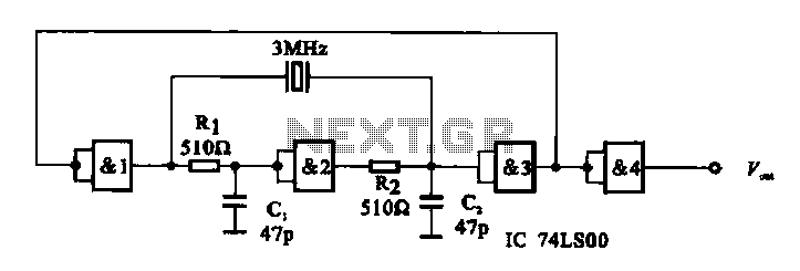
A crystal oscillator circuit is composed of several gates. Figure (A) illustrates a crystal oscillator circuit operating at 1 MHz, while Figure (B) depicts a 20 MHz crystal oscillator circuit. Figure (C) represents a variable crystal oscillator circuit with...
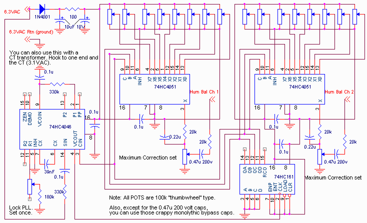
This report outlines the operation and adjustment of a Phase Locked Loop (PLL) hum cancellation circuit designed to reduce residual hum from amplifiers. This circuit is particularly useful for Directly Heated Triode (DHT) amplifiers with AC-operated filaments, where a...
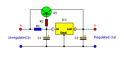
This is a compact and highly functional circuit that can be constructed on a veroboard. Voltage regulators such as the LM708 and LM317 series (among others) may occasionally require a load. The circuit utilizes voltage regulators, which are essential components...

Dual power for each load refers to the operation of two power supplies working simultaneously to handle the electrical load. In the event of a power outage, a contact switch automatically closes all load circuits that are not powered...
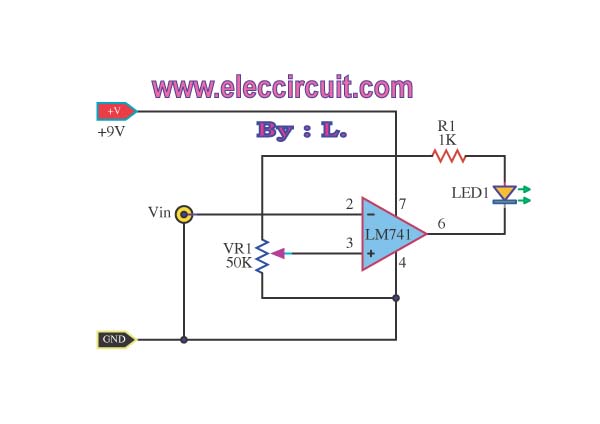
This simple low voltage tester circuit can be used to monitor batteries and other voltage sources for issues, utilizing an LED display and alarm sound. The low voltage tester circuit is designed to provide a reliable method for monitoring the...
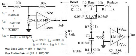
This topic continues from the more general Passive Tone Control circuit, which begins using only passive filters. This circuit follows the previous design, although the component values are different and in an alternate configuration. An audio tone control combines...