
22 watt car subwoofer amplifier

This circuit is structured to enhance the audio experience in automotive environments by effectively integrating a subwoofer into the existing sound system. The use of the Philips TDA1516BQ integrated circuit as a power amplifier is significant due to its efficiency and compact design, which minimizes the number of external components required.
The input stage of the circuit is designed to accept the line-level output from the car stereo, which is then processed through a level control to adjust the signal strength before buffering. The buffer stage is essential for maintaining signal integrity and preventing loading effects on the stereo output. The inclusion of a phase reversal switch (SW1) allows for flexibility in speaker phase alignment, which is crucial for achieving optimal sound quality and coherence in the audio reproduction.
The low-pass filter configuration is vital for subwoofer operation, as it ensures that only the desired low-frequency signals are sent to the subwoofer while filtering out higher frequencies that could cause distortion. The adjustable cutoff frequency, ranging from 70 Hz to 150 Hz, provides the user with the ability to tailor the subwoofer's response to match their specific listening preferences and the acoustics of their vehicle.
The voltage stabilization circuit composed of Q2, R17, and C9 is a critical addition, ensuring that the input and filter stages receive a stable voltage supply. This stability is essential for maintaining consistent performance and preventing noise that could arise from fluctuations in the power supply, particularly in the automotive environment where electrical noise is prevalent.
Overall, this subwoofer circuit design represents an effective solution for enhancing the bass response in car audio systems, combining simplicity, efficiency, and adaptability to meet the needs of automotive audio enthusiasts.This Simple subwoofer circuit is designed to be connected to an existing car stereo amplifier, adding that often require extra "punch" to music by driving a subwoofer. As the very low frequencies are omnidirectional, a single amplifier is necessary to promote the dedicated speaker.
The power amplifier using a Philips IC BTL TDA1516BQ requiring a v ery low number of components and capable of delivering about 22 W into a 4 ohm load on the battery voltage of 14. 4 standard car. The signals from the stereo line output amplifier car stereo mix in the entry, after the control level, the signal enters the buffer and can be IC1A reversed phase through SW1.
This control can be useful to allow the subwoofer to be in phase with the speakers in your car radio today. Then a variable 12dB/octave filter low pass frequency around IC1B, Q1 and components listed below, which allows precise adjustment of the low pass rate of 70 to 150Hz.
Q2, R17 and C9 form a simple voltage stabilizer for the input and filter circuits, useful to prevent interaction of the positive rail power amplifier to the low-level sections. 🔗 External reference
Related Circuits
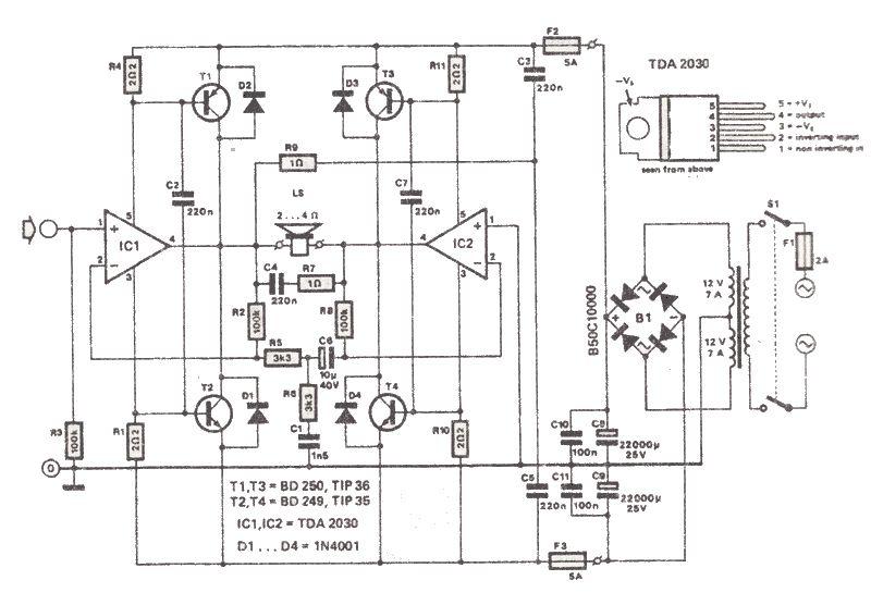
The TDA2030 is a low-cost audio power amplifier capable of delivering high output audio power up to 200 watts with a load impedance of 2 to 4 ohms. This high-power audio amplifier is built around the TDA2030 audio amplifier...
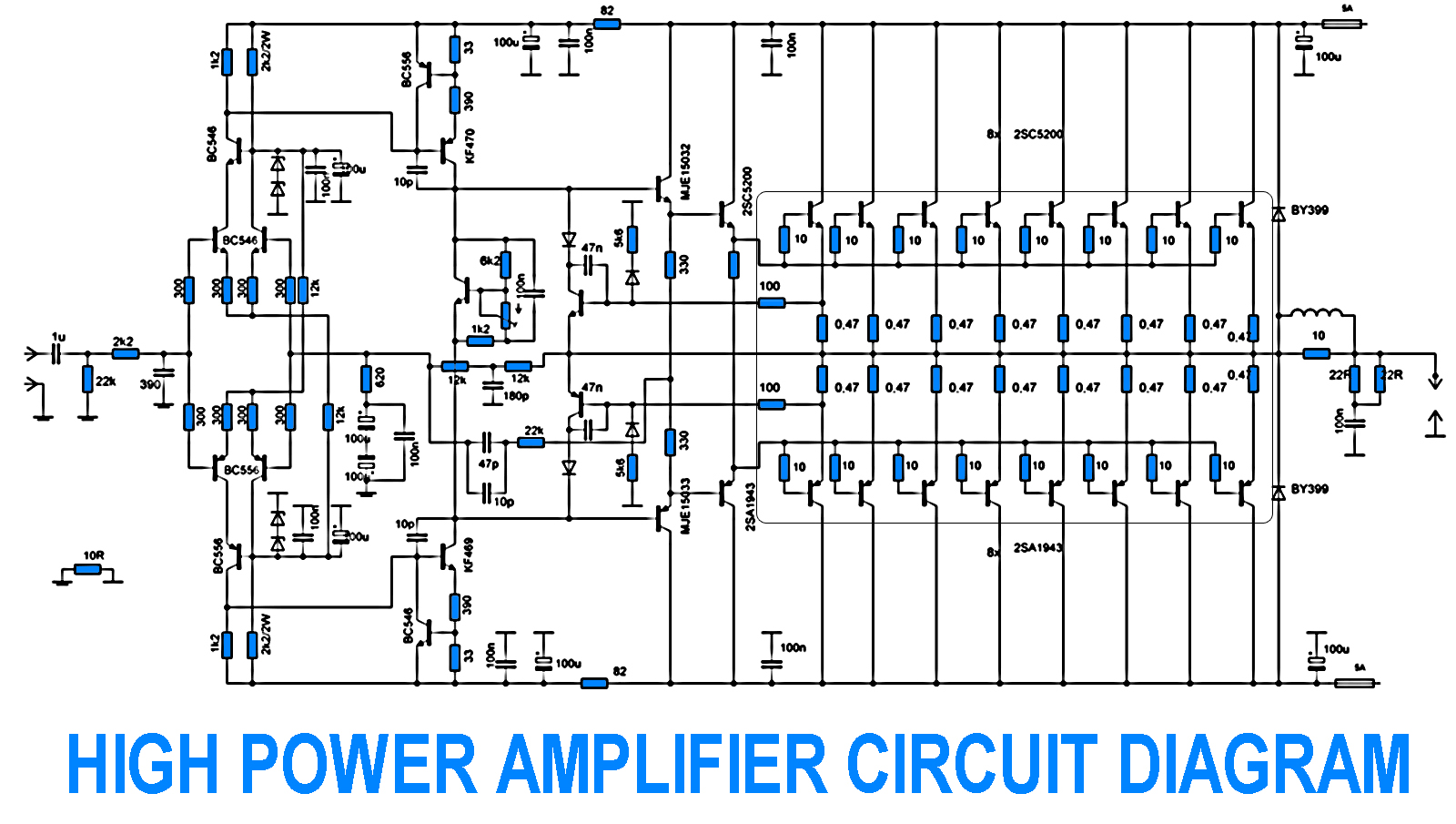
700W Amplifier. Adjusting the amplifier power to 700W appears straightforward, yet it is essential to consider the adjustment of the driving transistors and the frequency offset engagement. It is necessary to modify the current protection circuit that safeguards the...
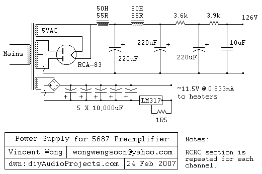
The RCA-83 rectifier utilizes 5VAC for the filament supply. The heaters for the 5687 tubes are powered by a full bridge rectifier consisting of MUR860 diodes, followed by five 10,000µF Elna capacitors. Current regulation is achieved through an LM317...
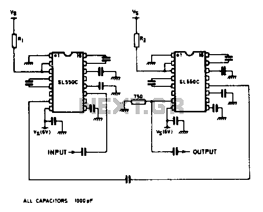
A wideband high gain configuration using two SL550s connected in series. The first stage is connected in a common emitter configuration, while the second stage is a common base circuit. Stable gains of up to 65 dB can be...
Simple and low cost. The optimal supply voltage is around 50V, but this amp works from 30 to 60V. The maximal input voltage is around 0.8 - 1V. As you can see, in this design the components have a...
The XLR connector facilitates the connection of the microphone's output to the preamplifier circuit. This preamplifier was designed and constructed by Electrical Engineers using discrete components. The signal from the preamplifier is subsequently fed to the Maxim Class-D amplifier....