
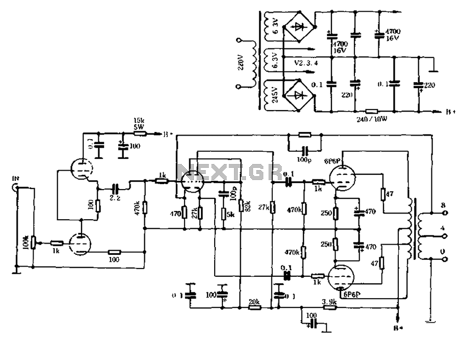
Tube Preamplifier 5687 Led Biased

The RCA-83 rectifier circuit is designed to provide a stable and regulated power supply for a high-fidelity audio preamplifier. The use of 5VAC for the filament supply indicates a low-voltage, high-current approach to heating the filaments of the 5687 tubes, ensuring optimal performance while minimizing noise. The full bridge rectifier configuration utilizing MUR860 diodes effectively converts the AC voltage into DC, while the five 10,000µF Elna capacitors serve to filter and smooth the rectified output, providing a stable voltage for the tube heaters.
Current regulation is critical in maintaining the performance of the 5687 tubes, and the implementation of the LM317 regulator with a 1.5Ω resistor allows for precise adjustment of the output voltage. The target voltage of approximately 11.5V for the tubes indicates a design choice aimed at achieving starved filament operation, which can enhance the linearity and overall sound quality of the audio signal.
The incorporation of an Omron timer to delay the B+ voltage serves as an important safety feature, ensuring that the RCA-83 mercury rectifier reaches operational temperature before high voltage is applied, thus preventing potential damage to the tubes and other components. The separation of the last two RC sections for each channel allows for independent control of the frequency response and stability of the audio signal, although future modifications to implement a constant current source (CCS) may further improve performance by providing consistent biasing across both channels.
The use of a polystyrene capacitor for the 10µF component is notable, as polystyrene capacitors are known for their low distortion and excellent frequency response, making them suitable for audio applications. The inclusion of 50H chokes in the design indicates an effort to further reduce power supply ripple and improve overall circuit performance.
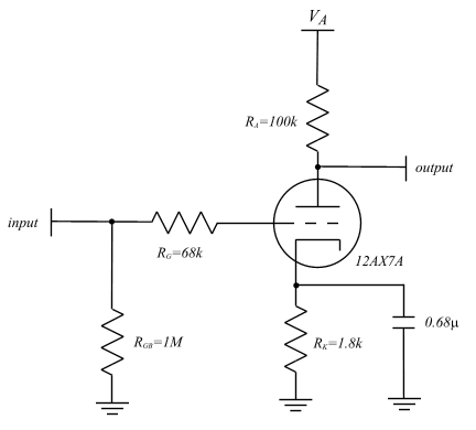
The preamplifier section's design, featuring a double section of the 5687 tube, is aimed at achieving lower effective tube impedance, which is beneficial for driving the Tamura A4717 5k output transformers. Each section's grid stopper and LED biasing are carefully chosen to optimize the performance of the tubes, ensuring that they operate within their linear range at 115V, -4V, and 25mA. The transition from AC to DC for the filament supply effectively mitigates hum, enhancing the overall audio quality of the preamplifier. The schematic representation of the preamplifier section, as indicated in Figure 01, serves as a valuable reference for understanding the circuit layout and interconnections among components.The RCA-83 rectifier makes use of 5VAC for the filaments. The heaters for the 5687 tubes are provided from a full bridge of MUR860 diodes, followed by 5 x 10, 000uF Elna caps. 830mA of current regulation is supplied using a LM317 regulator plus a 1R5 resistor between ADJ plus VOUT pins.
Votlage to the tubes is about 11. 5V, so I am actually running starved filaments. The power supply makes use of one RCA-83 mercury rectifier. An Omron timer is used to delay the B+ in order to permit the rectifier to warm up. The last 2 RC sections (3k6, 220uF, 3k9, 10uF) are separate for each channel, but in future I plan to remove that plus use a CCS for each channel instead. The 10uF capacitor is polystyrene. Yes, those are 50H chokes! The preamplifier makes use of the double section of a 5687 tube for each channel, with each section using it`s own grid stopper (220R) plus it`s own pair of green LED for a 4V bias.
The double section is used so as to lower the effective tube impedance, leading to better compatibility with the Tamura A4717 5k output transformers. The 5687 tubes are operated at 115V, -4V plus 25mA, which is one of the more linear regions for a 5687.
Initially, I attempted AC for the filaments plus the result was far much hum, so DC is used for the heaters. The schematic of the preamplifier section is shown in Figure 01. 🔗 External reference
Related Circuits
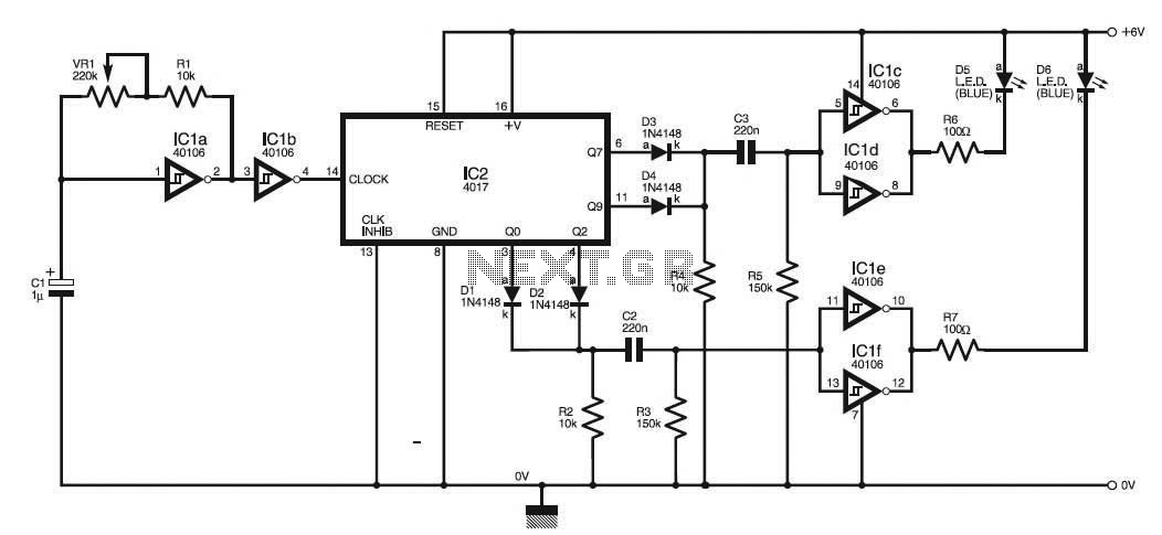
This circuit simulates the flashing strobe lights of British police cars by alternating the lights. The IC1a functions as a square wave oscillator with an adjustable frequency controlled by VR1 to achieve the desired effect. The circuit utilizes an...
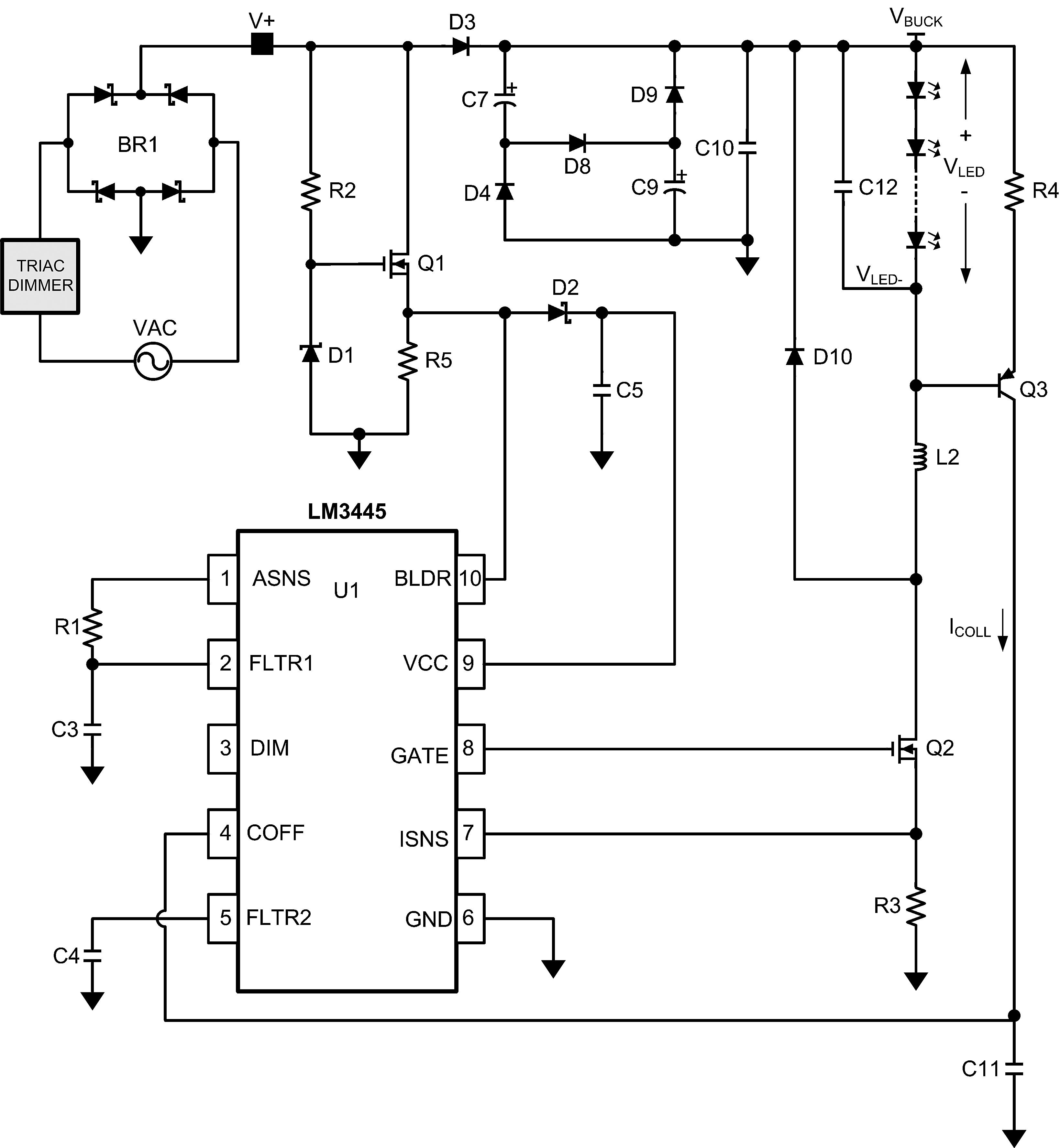
The LM3445 is an adaptive constant off-time AC/DC buck (step-down) constant current controller designed for compatibility with triac dimmers. The LM3445 is a specialized integrated circuit that functions as a constant current controller in AC/DC applications, particularly suited for LED...
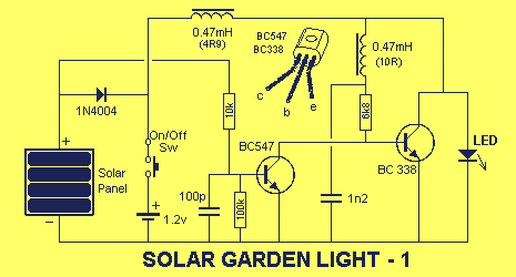
The circuit consists of two stages. The first stage is a switch or cut-off device. It detects a voltage above 0.7V from the solar panel, and the resistance between its collector-emitter terminals reduces to a very small value. The...
The self-generated bias amplifier tube is designed for each tube individually to alleviate the challenges faced by amateur conditions in paired amplifiers. It includes a separate DC filament power supply, which minimizes the risk of induced cross-linking and enhances...
The concept of an AC model for the triode is presented, and the equivalent circuit technique is described. Theoretical calculations for amplifier gain and frequency response are derived and compared to simulation results in the SPICE3 environment, showing good...
This is a universal version of the four-digit alarm control keypad. The design has been modified to free up the relay contacts, allowing the circuit to function as a general-purpose switch. A single pole changeover (SPCO) or single pole...