
amplifier circuit

The circuit begins with an XLR connector, which is commonly used in professional audio applications due to its balanced signal capabilities. The microphone connects to this XLR connector, allowing for a stable and noise-resistant transmission of audio signals. The output from the XLR connector is routed to a preamplifier circuit, which has been meticulously designed using discrete components to ensure high fidelity and minimal noise amplification.
The preamplifier amplifies the low-level microphone signal to a more manageable level suitable for further processing. This amplified signal is then fed into a Maxim Class-D amplifier, known for its efficiency and compact size. Class-D amplifiers operate by rapidly switching on and off, which allows for high power output with reduced heat generation.
Following amplification, the output signal undergoes low-pass filtering. This filtering process is crucial as it removes high-frequency noise and ensures that only the desired audio frequencies reach the speaker. The low-pass filter typically consists of passive components such as resistors and capacitors, which are configured to allow signals below a certain frequency to pass while attenuating higher frequencies.
In this design, the system does not utilize stereo transmission, which provides an opportunity to utilize the unused channel of the Class-D amplifier. This feature allows for a versatile approach to audio signal routing, enabling the opposite transmission path to be employed for additional functionalities, such as sending audio signals back to the microphone or integrating with other audio processing equipment.
The overall schematic effectively represents both inbound and outbound communication links, showcasing the flow of audio signals from the microphone to the speaker and allowing for flexible audio routing options within the system. This design exemplifies a robust and efficient audio processing solution, suitable for various applications in professional audio environments.The XLR connector allows us to connect the microphone`s output to our preamplifier circuit. This preamplifier was designed and built by our Electrical Engineers using discrete components. The preamplifier`s signal is then fed to the Maxim Class-D amplifier. The output is low-pass filtered and delivered to the speaker. Because we are not transmitti ng our signals in stereo, we will have the ability to utilize the unused channel of the Class-D amplifier for the opposite transmission path. This general schematic represents both the inbound and outbound communications link. 🔗 External reference
Related Circuits
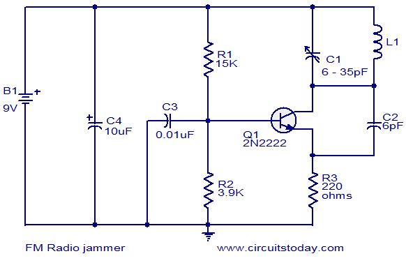
The FM jammer circuit diagram transmits VHF signals. Normally, the powerful oscillation of the circuit interrupts FM signals. Jammers are banned in many regions. The FM jammer circuit operates by generating a strong VHF (Very High Frequency) signal that disrupts...
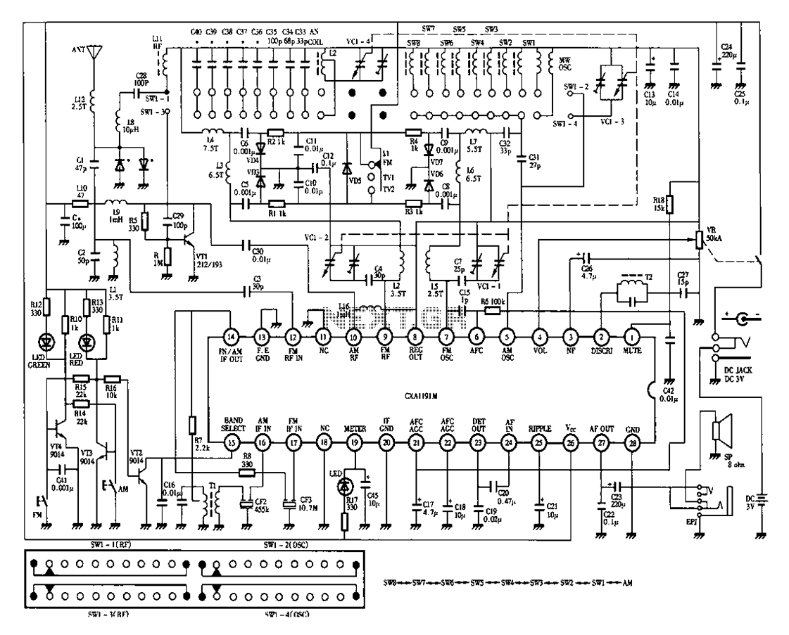
Desheng 1012 is a 12-band radio circuit diagram that covers FM, MW, SW, and TV sound frequencies. The Desheng 1012 radio circuit is designed to receive a wide range of frequencies across multiple bands, including FM (Frequency Modulation), MW...
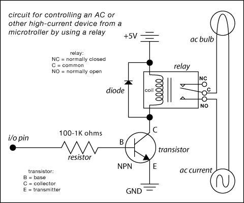
Here are some circuit diagrams for driving relays from a microcontroller. Ensure the use of a 5-volt relay (this refers to the coil, not the load circuit) and verify that the relay has a sufficient rating for the load...
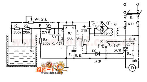
The controller consists of a liquid level sensor, a trigger controller, and a step-down rectifier circuit. The water level detection poles labeled a, b, and c form a bias circuit, functioning as a water level detector with components W1,...

The objective of the circuit is to create an electronic dice using the functionality of a 555 timer integrated circuit operating in astable mode. The electronic dice circuit utilizes a 555 timer configured in astable mode to generate a series...
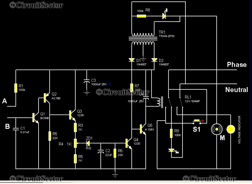
This is an automatic water tank controller designed to manage the operation of a water pump using a 12V 10A relay. When the water level in the tank creates a short circuit between points A and B in the...