
22 Watt Stereo audio Amplifier

This circuit is designed to deliver substantial power output suitable for automotive or residential applications. The fundamental architecture typically involves a power supply, switching components, and output stage configured to handle the required load.
The power supply section may consist of a transformer or a DC power source, which is responsible for converting the input voltage to the desired output level. A rectifier circuit, composed of diodes, is often employed to convert AC to DC if necessary.
Switching components, such as transistors or MOSFETs, are utilized to control the flow of current through the circuit. These components should be chosen based on their current and voltage ratings to ensure they can handle the load without overheating or failing.
The output stage may include capacitors for filtering to smooth out voltage fluctuations and provide a stable output. Inductors might also be incorporated to reduce noise and improve performance.
To achieve optimal performance, it is crucial to minimize lead lengths between components. Short leads reduce resistance and inductance, which can adversely affect circuit efficiency and performance. Proper layout and grounding techniques should be employed to further enhance the circuit's reliability and functionality.
Overall, this circuit serves as a versatile solution for power amplification in various applications, ensuring effective energy delivery for both automotive and home use.This circuit is very basic to build and puts out great power for your car or home. Keep all leads as short as possible. 🔗 External reference
Related Circuits
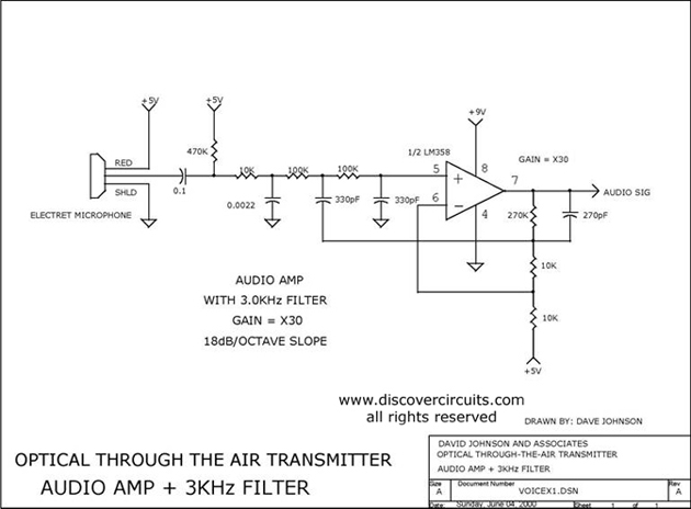
Audio amplifier with a 3 kHz filter. This circuit serves as the audio amplification section for a complete optical transmitter. It amplifies and filters voice audio signals from an electret microphone. The audio amplifier circuit is designed to enhance the...
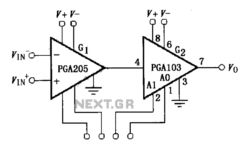
The circuit depicted in the figure comprises a PGA103 programmable gain instrumentation amplifier. This design utilizes the PGA205 and PGA103 in a cascading configuration, resulting in a total gain for the amplifier. The gain is determined by the product...
A year ago, a Class-D amplifier was designed based on the TAS5162, PCM1808, and TAS5086. Over the past year, several hundred samples were produced for sale to radio amateurs. Most devices function correctly without issues reported by consumers. However,...
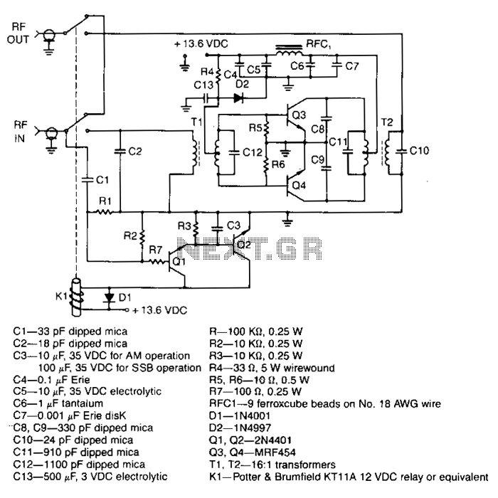
This amplifier delivers a nominal output power of 140 watts peak envelope power (PEP) when fed with input levels as low as 3 watts. Both the input and output transformers feature a 4:1 turn ratio and a 16:1 impedance...
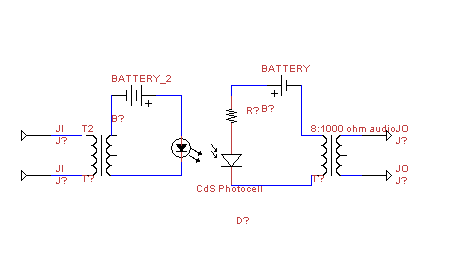
This circuit transmits audio information using light waves. It employs amplitude modulation (AM) to vary the intensity of an LED, which is detected by a cadmium sulfide photocell that changes its resistance based on light intensity. The circuit includes...
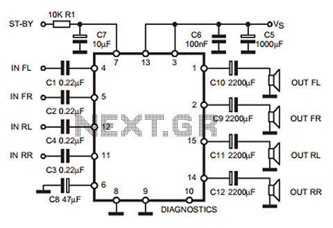
The following circuit illustrates a 35W quadruple amplifier and a 2 x 25W bridge amplifier based on the TDA7375 integrated circuit (IC). This circuit requires a minimal number of external components. Although initially designed for car applications, it can...