
TDA7375 Car Audio Amplifier Circuit

The TDA7375 integrated circuit is designed for high efficiency and flexibility, making it suitable for various audio amplification applications beyond automotive use. The 35W quadruple amplifier configuration leverages the IC's capabilities to drive multiple channels, making it ideal for multi-channel audio systems. The bridge mode configuration, which combines two amplifier channels to produce higher power output, is particularly beneficial for driving larger speakers or subwoofers, enhancing the overall audio experience.
The circuit design emphasizes a minimal external component requirement, which simplifies the assembly process and reduces potential points of failure. The fully complementary output stage allows for improved linearity and reduced distortion, ensuring high-quality audio reproduction. The fixed gain configuration streamlines the design, eliminating the need for external gain-setting resistors, which can complicate the circuit and introduce variability in performance.
The onboard clip detector is a notable feature that helps prevent distortion by monitoring the output signal and providing feedback to adjust the gain accordingly. This ensures that the amplifier operates within its optimal range, delivering clear sound without unwanted clipping. Additionally, the fault diagnostics capability is essential for troubleshooting during the installation of car audio systems, allowing technicians to quickly identify and rectify wiring errors or component failures, thereby enhancing reliability and user satisfaction.
In summary, the TDA7375-based amplifier circuit is a versatile solution for audio amplification, combining high power output, minimal component count, and advanced features that cater to both automotive and general audio applications.The following circuit shows about 35W quadruple amplifier and 2 x 25W bridge amplifier based on the TDA7375 IC, this circuit requests the minimum of external components. Although the first conception went to car applications, to give him/it in a great variety of applications of low potency.
That integrated circuit is ideal in the situation in tha t is wanted a reasonable potency and with a Power tension relatively low for your operation. That circuit drawn below it uses the basic configuration of quadruple amplifier, but using a configuration in bridge, it can be obtained about 4 times the maximum potency. In that configuration of quadruple amplifier it can be used as amplifier end of systems surround IC TDA7375 is a new technology class AB car amplifier able to work either in dual bridge or quad single ended configuration.
The exclusive fully complementary structure of the output stage and the internally fixed gain guaranteesthe highest possible power performances with extremely reduced component count. The on-board clip detector simplifies gain compression operation. The fault diagnostics makes it possible to detect mistakes during car radio set assembly and wiring in the car.
🔗 External reference
Related Circuits
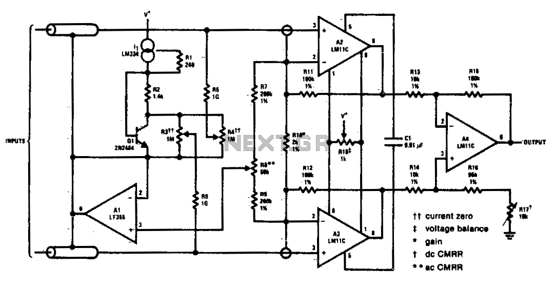
This circuit includes input guarding, cable bootstrapping, and bias current compensation. Differential bandwidth is reduced by Cl, which also makes common-mode rejection less dependent on the matching of input amplifiers. The described circuit features several critical components designed to enhance...
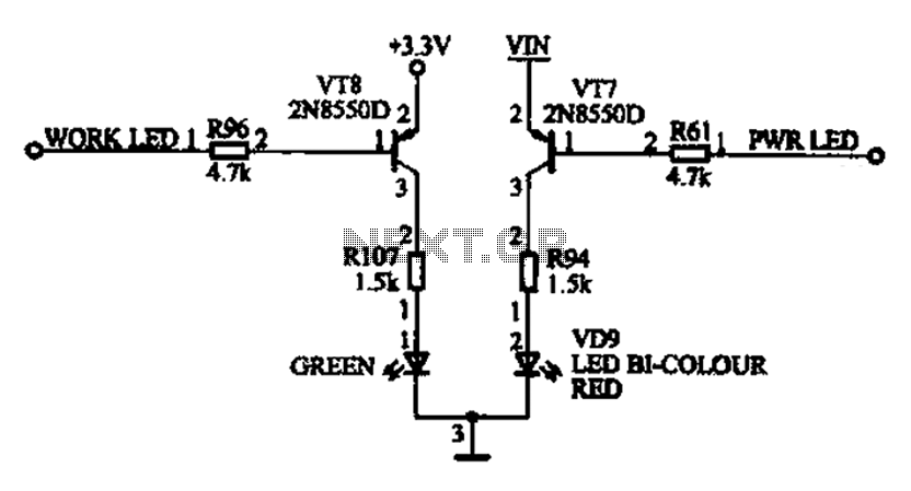
The ACER PM02 MP4 machine features a voltage status indicator circuit. When power is supplied, a red LED illuminates, indicating that the device is powered on. Upon entering operational mode, a green LED lights up. The voltage status indicator circuit...
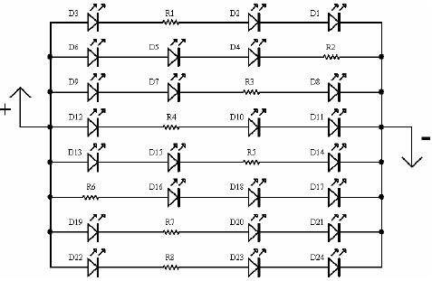
A light-emitting diode (LED) lamp is a solid-state lighting device that utilizes light-emitting diodes as its light source. LEDs are a cost-effective and convenient choice for various lighting applications. They are available in an extensive range of colors, styles,...
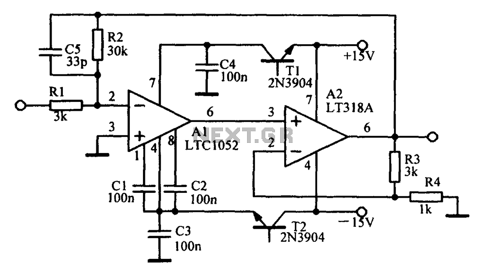
Amplifying circuit diagram to enhance the output current and voltage. An amplifying circuit is designed to increase the amplitude of an input signal, resulting in a higher output current and voltage. This type of circuit is commonly utilized in various...
Building battery boxes for the Speedster. Although this topic may not seem thrilling, builders converting vehicles to electric drive often discover that the process of making a car run on battery power is relatively straightforward. However, about 50% of...
This circuit uses two quad op-amps to form an eight LED audio level meter. The op-amp used in this particular circuit is the LM324. It is a popular IC and should be available from many parts stores. More: The...