
220V AC Powered White Led Lamp

The described circuit utilizes a capacitive step-down method to reduce the high voltage alternating current (AC) from the mains supply to a lower voltage suitable for powering light-emitting diodes (LEDs). The core components include an X-rated capacitor (CX) and a bridge rectifier formed by diodes D1 through D4. The primary function of CX is to lower the AC voltage through capacitive reactance, which is an essential feature for ensuring that the voltage levels are safe for subsequent processing.
Once the voltage is reduced, the AC current is directed through the bridge rectifier, which converts the alternating current into direct current (DC). This rectified DC is not yet suitable for powering LEDs directly, as it contains ripples that can affect performance. Therefore, capacitor C1 is employed to smooth out these ripples, providing a stable low voltage DC output that can effectively power the LEDs.
Resistor R1 is strategically included in the circuit to facilitate the safe discharge of any residual voltage stored in capacitor CX when the power supply is disconnected. This precaution is critical in preventing electric shock hazards, especially since the circuit interfaces directly with mains voltage.
Additionally, the circuit design allows for flexibility in the number of LEDs that can be connected. By adjusting the resistance value of R2, more LEDs can be added to the circuit without compromising performance. However, it is imperative to maintain safety protocols, as the circuit operates at mains voltage levels. Users must refrain from touching any components while the circuit is energized to mitigate the risk of electrical shock.
Overall, this circuit effectively combines safety and functionality, making it suitable for applications requiring reliable illumination while adhering to safety standards.It can give ample light even for reading purpose. Capacitor CX along with diodes D1 through D4 forms the AC step down circuit. CX reduces high voltage AC from mains to a low voltage AC which is rectified by the diodes D1-D4. Capacitor C1 removes ripples from AC so that low voltage DC is available to power the LEDs. CX is the X rated AC capacitor th at reduces AC voltage through capacitive rectance property. Resistor R1 is very important to remove the stored voltage from CX when power is switched off. This prevents lethal shock. More LEDs can be added by reducing the value of R2. Since the circuit is directly connected to mains, take utmost care to avoid shock. No components should be touched when it is connected to mains. We aim to transmit more information by carrying articles. Please send us an E-mail to wanghuali@hqew. net within 15 days if we are involved in the problems of article content, copyright or other problems. We will delete it soon. 🔗 External reference
Related Circuits

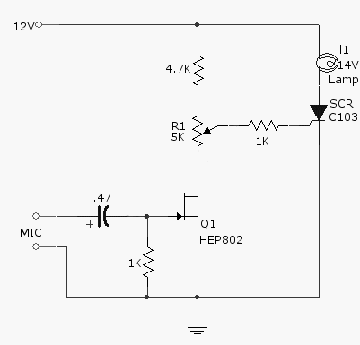
The CMOS 4001 consists of four independent two-input NOR gates. These gates are organized into two pairs. Gates 1 and 2 are connected to form a latching circuit. When the alarm is triggered, they will latch and activate the...
This article presents basic circuits for pulsing infrared LEDs and low-power visible semiconductor lasers utilizing inexpensive and readily available components. Numerous interesting and practical applications are referenced, alongside several online resources. The focus of the article is on the...
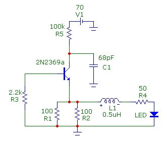
This simple circuit, as shown in the schematic diagram, activates a switch using sound. It can be utilized for various applications, such as an automatic sound-controlled disco light or a car's LED light show. The transistor Q1 amplifies the...
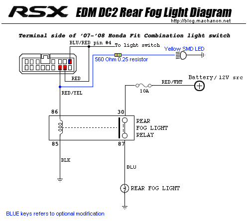
This guide provides instructions for installing an EDM/UKDM Honda Integra DC2 rear fog light on a 2005-2006 Acura RSX. The installation of an EDM/UKDM Honda Integra DC2 rear fog light on a 2005-2006 Acura RSX involves several key steps to...

This circuit is for a temperature controlled constant current battery charger. It works with NICD, NIMH, and other rechargeable cells. The circuit works on the principle that most rechargeable batteries show an increase in temperature when the cells become...
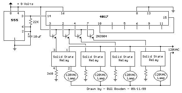
This circuit is basically the same as the 10 channel LED sequencer with the addition of solid state relays to control the AC lamps. The relay shown in the diagram is a Radio Shack 3 amp unit (part no....