
sound activated lamp relay switch

This sound-activated switch circuit is designed to respond to audio signals, providing an effective solution for various sound-controlled applications. The core component of this circuit is the transistor Q1, which serves as an amplifier for the audio input received from the microphone. The microphone captures sound waves, converting them into an electrical signal, which is then amplified by Q1. This amplification is critical, as it allows the circuit to respond to relatively low sound levels.
The resistor R1 plays a crucial role in determining the sensitivity of the circuit. By adjusting R1, the user can set the threshold level for the audio signal that will trigger the subsequent components. When the amplified audio signal exceeds approximately 0.7 volts, it activates the silicon-controlled rectifier (SCR). The SCR is a semiconductor device that allows current to flow in one direction when triggered, effectively acting as a switch.
The load connected to the output of the SCR can vary depending on the application. In the described configuration, lamp I1 serves as a visual indicator, lighting up in response to sound. However, by replacing lamp I1 with a relay, the circuit can control higher power devices. This relay can handle larger currents and voltages, enabling the activation of high-wattage lamps or other electrical appliances that require more power than the original lamp.
In summary, this circuit demonstrates a practical application of sound detection and amplification, providing a versatile solution for creating sound-activated devices. The ability to adjust sensitivity and control larger loads makes it suitable for various consumer electronics and automation projects.This simple circuit shown int the schematic diagram actives the switch using sound. We can use this circuit for various applications, such as automatic (sound-controlled) disco light or car`s LED light show. The Q1 amplify the audio from mic. The R1 is used to adjust the peak of signal to greater than about 0. 7 volts, act as sensitivity adjuster. A certain level, the signal coming from microphone, after amplification by Q1, will trigger the SCR and light lamp I1. If we change the lamp with a relay, then we can get a sound-activated relay/switch, which can be used to control more powerful / high wattage high voltage lamps.
🔗 External reference
Related Circuits
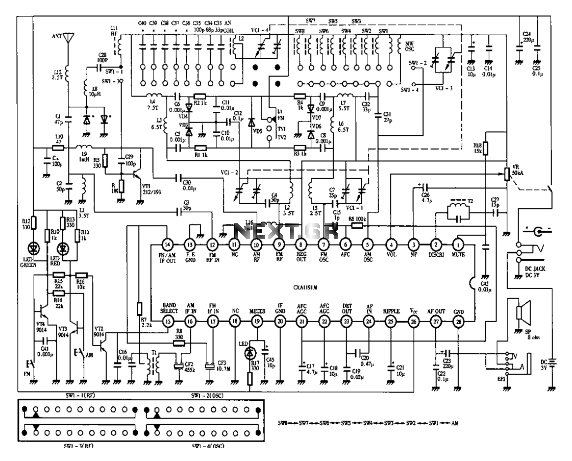
Desheng 1012 is a 12-band radio circuit diagram that covers FM, MW, SW, and TV sound frequencies. The Desheng 1012 radio circuit is designed to receive a wide range of frequencies across multiple bands, including FM (Frequency Modulation), MW...

The circuit utilizes a 555 integrated circuit (IC) functioning as an astable multivibrator. When a positive 9 volts is applied to pin 8, the circuit generates sound through a speaker. The connection to pin 8 is routed through a...
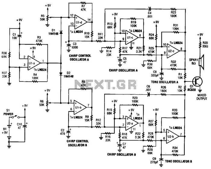
This circuit generates the sound of two canaries singing in a cage. Two LM324 quad amplifiers constitute seven oscillators. One oscillator serves as an on/off control, while the remaining six produce the sounds of two canaries. A 9-V supply...
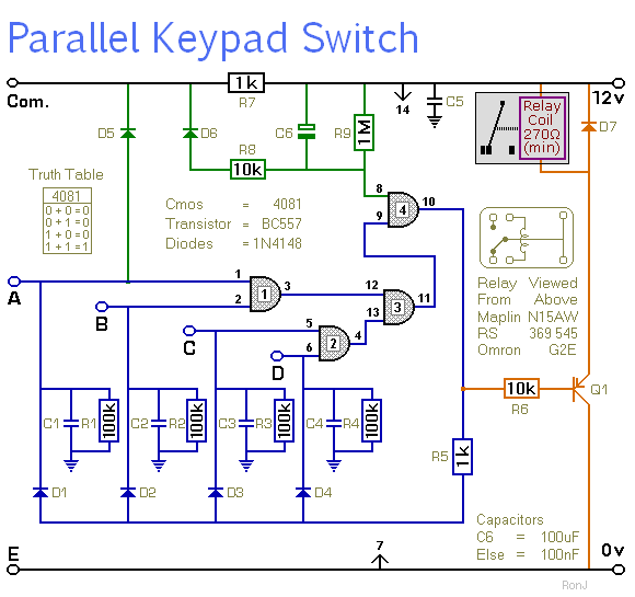
This is a universal four-digit keypad-operated switch with a unique feature. Instead of entering the security code one digit at a time, all four keypad buttons must be pressed simultaneously. This means the four numbers must be entered in...
The lack of compensation facilitates the processes of development and testing. The figure of 6 billion frequently appears as the estimated number of cell phones in use globally. Published estimates indicate an average. The discussion of compensation in electronic circuits...
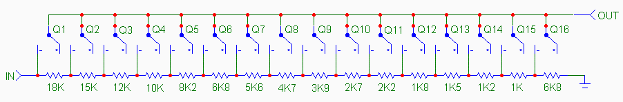
The traditional potentiometer is implemented with an electrical contact that slides over a resistive layer. An example of a well-known audio-grade potmeter is the Alps Blue. A high-end (good and costly) alternative is the rotary switch. This device consists...