
220V LED Flasher

The 200W lamp flasher circuit is designed to provide adjustable flashing capabilities for a lamp, making it suitable for decorative lighting or signaling purposes. The primary component, a variable resistor (PR1), allows the user to fine-tune the flashing frequency, while the second variable resistor (PR2) controls the duty cycle, thereby altering the duration of the on and off states of the lamp. This feature is particularly useful for applications requiring specific lighting effects.
In the LED flasher circuit, the use of two transistors enables efficient switching of high-brightness LEDs, enhancing visibility. The flip-flop operation adds reliability to the circuit, ensuring that the LEDs can be toggled on and off in a controlled manner. The component list provides essential values for resistors and capacitors, ensuring that the circuit operates within designed specifications.
The touch dimmer circuit, utilizing an 8-pin CMOS IC, represents a modern approach to controlling incandescent lamps. The touch interface simplifies user interaction, allowing for seamless adjustment of light intensity without mechanical switches. This circuit's design is optimized for low power consumption and responsiveness to user input.
The doorbell circuit, featuring an NE555 timer, serves dual purposes: it provides an audible alert while also incorporating visual elements through flashing LEDs. The astable multivibrator configuration allows for adjustable frequencies, making it adaptable to various signaling applications.
The delay circuit is an innovative solution for maintaining illumination in situations where immediate power loss occurs. By integrating a timer mechanism, it allows for a gradual shutdown of connected devices, enhancing user experience and safety.
Finally, the backup power circuit is crucial for maintaining functionality during power outages. By utilizing NI-CD batteries, this circuit ensures that essential lighting remains operational, providing a reliable temporary power source. The continuous connection to the mains socket allows for automatic recharging, making it a practical solution for homes and businesses alike.This is the 200W lamp flasher circuit diagram. The frequency/speed of the lamp flashing can be adjust with the range of 1Hz to 5Hz. You can use the PR1 variable resistor (trimpot) to adjust the flashing speed. The duty cycle of lamp flashing can be adjusted using PR2 variable resistor. The DC input power supply. The following is LED Flasher circu it which use 2 transistors for LED switching. The circuit works similar to flip-flop operation. Component Parts List: R1 = 10M ohm R2 = 1K - 100K ohm R3 = 470 ohm C1 = 0. 47 F - 10 F/25V D1 = 1N914 Q1 = 2N3904 Q2 = 2N3906 Led = High Brightness. Here the 220V AC lamp touch dimmer circuit. By only touching this touch dimmer you are able to increase the light intensity of incandescent lamps in three stages. The touch dimmer is designed all around 8-pin CMOS IC TT8486A/TT6061A especially produced for touch dimmer applications.
In the beginning, when mains switch is "on", the lamp. This is the door bell circuit with flashing LEDs to make the circuit more attractive. IC1 (NE555) is applied right here as being a clock generator. It is actually set up as an astable multivibrator whose frequency could be altered using the support of potensiometer VR1. The clock pulses received from IC1 are fed to. Following is a circuit you can use to delay an electronic device to be disabled. For example, you can connect this circuit to the lamp in your room. When you turn off the lamp with a switch on the circuit, the lamp will remain lit in a certain period of time, before the lamp really.
When the electric in your home/company has been shutted down for maintenance and or shutted down due to short circuit, you may need this circuit for backing up your electric power for temporary usage. This circuit is permanently plugged into a mains socket and NI-CD batteries are trickle-charged. When a power outage occurs, the lamp. 🔗 External reference
Related Circuits
The Battery Good checker. When the button is pressed, the green LED will glow if the battery voltage is above the preset threshold. This version has a higher parts count than the Battery Low version, but a bonus is...
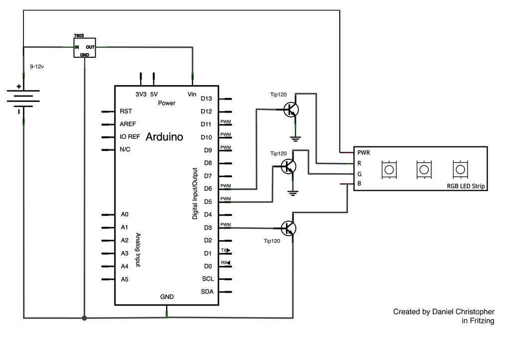
This document outlines the assembly of a circuit designed to pulse width modulate (PWM) a high-power RGB LED strip and program an Arduino to cycle through various colors. The high-power range is specified as 9-12 volts. The procedure includes...

This project involves a sequence of Ultra-Bright LEDs that light up briefly in a circular pattern, mounted on a CD. The LEDs flash for 15 milliseconds, followed by a one-second pause, creating a visually appealing effect. The brief flashes...

Opening SA changes the indicator lamp from a flashing to a steady-lit condition. The 6-V incandescent lamp on the collector of Q2 requires about 0.3 A. A 1 kΩ load resistor limits Q1's collector current to about 6 mA....

BKQ series automatic parallel controllers are specifically designed for small hydropower automation devices operating in parallel, with a capacity of 3200 kW and below, for both high and low pressure turbines. These controllers automatically adjust based on the generator...

This circuit operates between 150 to 165 MHz. The crystals used are Digi-Key Electronics Barrel Crystals of the CA-301 type, which are relatively inexpensive. Any fundamental crystal with a frequency between 14 and 17 MHz can produce an output...