
LED Battery Checkers


When voltage drops below the preset threshold, the voltage on the wiper of R2 drops below 2.5 volts, and the TL431 conducts less current, only up to about 1 milliamp, and the anode voltage rises until the LED conducts.
I tested this with a 6 volt threshold rather than a 5.4 volt threshold. When adjusted for a 6 volt threshold, the LED turns on at 6.0 volts and then slowly fades out as the battery voltage decreases, until it reaches about 2.5 volts, when the LED is too dim to see. The LED is off above 6.0 volts, but (for reasons I have not investigated) the LED comes back on at voltages above 8.35 volts. The come back on voltage is proportional to the threshold setting, thus, if the circuit were adjusted to turn on the LED when the voltage dropped below 12 volts, the LED would also come on at voltages above (8.35/6) x 12 = 16.7 volts.
The minimum voltage across the TL431 is 2.5 volts, which would still leave enough to illuminate D2 (which requires about 1.8 volts), so D1 was added to provide an additional 0.7 volt drop in series with D2 so that D2 will not illuminate when the TL431 is sinking the maximum current.
These circuits can also be adjusted for other battery voltages and other types of battery. This circuit should work well with Nickel Cadmium (ni-cd or nicad), Nickel Metal Hydride (NIMH) or other rechargeable as well as primary cells types such as Carbon-Zinc and Alkaline. Just make sure that you don't exceed the ratings of the parts for your particular application.
The practical minimum threshold voltage for the Battery Low circuit is about 3.5 volts while the practical minimum voltage for the Battery Good circuit is about 4.5 volts.
The Battery Good checker circuit employs a TL431 voltage reference as the core component for monitoring battery voltage levels. The circuit is designed to activate a green LED indicator when the voltage exceeds a specified threshold, which can be adjusted according to the battery type and application. The operational principle is based on the voltage divider formed by a potentiometer (R2) and the battery voltage, allowing for precise setting of the threshold.
When the button is pressed, the circuit checks the voltage across the battery. If the voltage is above the set threshold, the wiper of R2 will output a voltage greater than 2.5 volts, causing the TL431 to conduct and effectively shunt current away from the LED, keeping it off. Conversely, if the battery voltage falls below the threshold, the output from R2 drops below 2.5 volts, reducing the current through the TL431. This allows the anode voltage to rise, eventually enabling the LED to illuminate.
The circuit is capable of handling various battery chemistries, including lead-acid, Nickel Cadmium, Nickel Metal Hydride, and Alkaline batteries. It is essential to ensure that the components used are rated for the specific application to prevent damage or failure. The inclusion of a series diode (D1) helps to ensure that the LED (D2) does not illuminate under high current conditions, providing a safeguard for the circuit's operation.
The design allows for a minimum threshold voltage of approximately 4.5 volts for the Battery Good circuit, which can be tailored to suit the requirements of different battery types or applications. This flexibility makes the circuit a versatile solution for battery monitoring in various electronic devices.The "Battery Good" checker. When the button is pressed, the green LED will glow if the battery voltage is above the preset threshold. This version has a higher parts count than the "Battery Low" version, but a bonus is that it can drive an LED to be very bright, and the luminance is independent of the battery voltage.
The simple expedient of a jumper wire on the back of the board made it unnecessary to hold the button down for this photograph. Besides, my finger is not very photogenic. According to Mr. Lung, the lowest safe voltage across a lead acid battery while in long term storage is 2.0 volts per cell, or 6.0 volts for a 6 volt battery. Gates Energy Products, the load must be disconnected from a lead acid cell when the voltage reads 1.8 volts or less, in order to avoid damage.
For a 6 volt battery with three cells, this critical voltage is 3 x 1.8 volts = 5.4 volts. Choose your threshold depending upon your application. If there is a good chance that the battery will not be recharged soon after running down, be safe and go with the 2.0 volt per cell threshold. The TL431 has an internal threshold of 2.5 volts. Pot R2 is adjusted so that when the battery voltage equals the desired threshold, the wiper of R2 will be 1.25 volts.
When the voltage across the battery is above the preset threshold, the voltage at the wiper of R2 is above 2.5 volts, the TL431 conducts, shunting current away from the LED, keeping the LED off. When voltage drops below the preset threshold, the voltage on the wiper of R2 drops below 2.5 volts, and the TL431 conducts less current, only up to about 1 milliamp, and the anode voltage rises until the LED conducts.
I tested this with a 6 volt threshold rather than a 5.4 volt threshold. When adjusted for a 6 volt threshold, the LED turns on at 6.0 volts and then slowly fades out as the battery voltage decreases, until it reaches about 2.5 volts, when the LED is too dim to see. The LED is off above 6.0 volts, but (for reasons I have not investigated) the LED comes back on at voltages above 8.35 volts.
The "come back on voltage" is proportional to the threshold setting, thus, if the circuit were adjusted to turn on the LED when the voltage dropped below 12 volts, the LED would also come on at voltages above (8.35/6) x 12 = 16.7 volts. The minimum voltage across the TL431 is 2.5 volts, which would still leave enough to illuminate D2 (which requires about 1.8 volts), so D1 was added to provide an additional 0.7 volt drop in series with D2 so that D2 will not illuminate when the TL431 is sinking the maximum current.
These circuits can also be adjusted for other battery voltages and other types of battery. This circuit should work well with Nickel Cadmium (ni-cd or nicad), Nickel Metal Hydride (NIMH) or other rechargeable as well as primary cells types such as Carbon-Zinc and Alkaline. Just make sure that you don't exceed the ratings of the parts for your particular application. The practical minimum threshold voltage for the Battery Low circuit is about 3.5 volts while the practical minimum voltage for the Battery Good circuit is about 4.5 volts.
🔗 External reference
Related Circuits
The LM1036 is a DC-controlled circuit designed for tone adjustment (bass/treble), volume control, and balance. It is suitable for use in car radios, televisions, and audio systems. The circuit also incorporates loudness compensation. The LM1036 integrates several functionalities essential for...
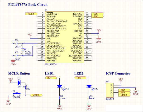
This project involves a basic LED blinking circuit utilizing the PIC16F877A microcontroller. It features two LEDs connected to the PIC16F877A, with the source code adapted from the 16F template. The circuit design consists of the PIC16F877A microcontroller, which serves as...
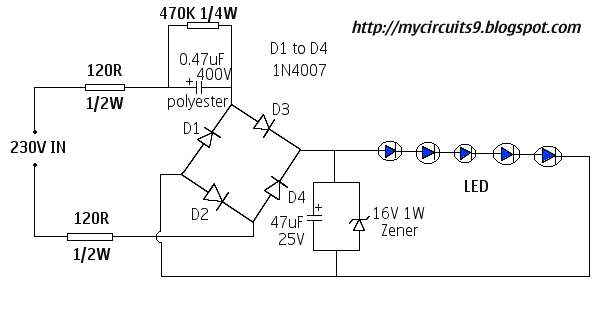
This document presents a 230V LED driver circuit that operates without a transformer. The circuit utilizes five LEDs, although the number can be increased as desired. The absence of transformers significantly reduces both the cost and size of the...
An LED flasher circuit can be constructed using a 555 integrated circuit (IC). The use of the 555 IC allows for greater flexibility in adjusting the flashing rate of the LED. This LED flasher circuit is similar to other...
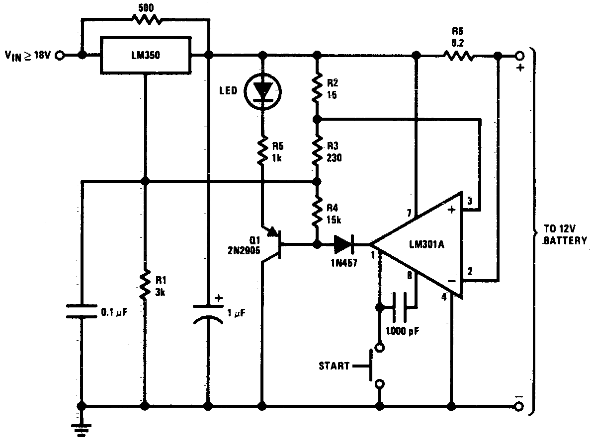
DC 12V Battery Charger Circuit Diagram. This circuit is a high-performance charger for gelled electrolyte lead-acid batteries. The DC 12V battery charger circuit is designed to efficiently charge gelled electrolyte lead-acid batteries, which are commonly used in various applications due...

This application note discusses the use of SEPIC power modules to supply the necessary power for driving high-brightness LED arrays. These arrays serve as display backlights and necessitate a wide dimming range. The SEPIC configuration offers an efficient and...