
Blinking LED Emulates Incandescent Bulb

The flashing LED circuit designed to mimic an incandescent lamp operates by simulating the gradual increase and decrease in brightness that is typical of traditional incandescent bulbs. This effect is achieved using a microcontroller or a simple timing circuit that modulates the current flowing through the LED.
The core components of the circuit include an LED, a resistor to limit current, and a timing element, which can be implemented using a capacitor and a transistor or through a microcontroller’s PWM (Pulse Width Modulation) capabilities. The LED is connected in series with a current-limiting resistor to prevent it from drawing excessive current, which could lead to damage.
To create the flashing effect, the circuit utilizes a timing mechanism that controls the on and off states of the LED. When the LED is turned on, the current flows through the resistor, causing the LED to light up. As the timing circuit triggers the LED to turn off, the current ceases, and the LED gradually dims. This dimming effect can be further enhanced by adjusting the timing parameters, allowing for a more realistic simulation of the incandescent lamp's warm glow.
The overall design can be expanded with additional features, such as adjustable brightness levels or varying flash rates, to better suit specific applications or user preferences. This circuit can be effectively used in decorative lighting, automotive applications, or any scenario where a warm, incandescent-like glow is desired from LED technology.This is flashing LED circuit emulate the turning of incandescent lamp. The characteristic of incandescent lamp is that they can`t abruptly change the.. 🔗 External reference
Related Circuits

The camera operation failure on the Nokia 2630 has a similar solution to that of the Nokia 2600c, as both devices share the same circuit board. This issue is typically caused by hardware damage or a broken line on...

A vertical column of LEDs is configured so that as the audio signal level rises, an increasing number of LEDs illuminate. The LEDs are arranged in increments of 6 dB. The circuit features a fast response time and a...

A DC-coupled multi-stage amplifier circuit consists of multiple stages of amplification using a DC-coupled configuration. Each stage utilizes NPN-type transistors, which are designed to maintain appropriate operating points at the base of each stage. As the signal progresses through...
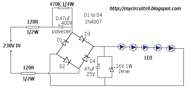
This document presents a 230V LED driver circuit that operates without a transformer. The circuit utilizes five LEDs, although the number can be increased as desired. The absence of transformers significantly reduces both the cost and size of the...
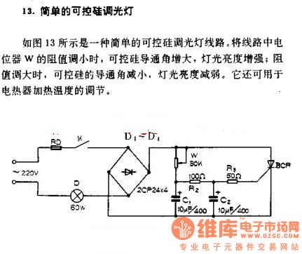
A simple silicon-controlled rectifier (SCR) dimmer circuit is depicted in Figure 13. This circuit is designed to control the brightness of lights. As the resistance in the potentiometer decreases, the conduction angle of the SCR increases, resulting in an...

The LTC3453 is a synchronous buck-boost DC/DC converter optimized for driving up to 4 white LEDs at a combined current of up to 500mA from a single Li-Ion battery input. The regulator operates in either synchronous buck, synchronous boost,...