
ld168 audio control circuit diagram of a voltage-controlled flash decoration

The LD168 circuit is designed to provide a visual representation of sound levels through the use of light-emitting diodes (LEDs). Each of the four outputs corresponds to different sound level thresholds, allowing for a clear indication of audio intensity. When the sound level reaches a specified point, the respective LED will illuminate, offering immediate feedback to the user regarding the audio output.
In terms of functionality, the LD168 can operate in two primary modes. The first mode utilizes direct LED drive, where the outputs are connected to the LEDs, allowing them to light up in response to the audio levels detected by the circuit. This mode is particularly useful in applications where real-time visual feedback is essential, such as in live sound environments or recording studios.
The second mode of operation involves the use of a thyristor drive, which enables the circuit to control higher power lantern lights. This feature is beneficial for applications that require more substantial lighting effects or where the use of standard LEDs would be insufficient. The thyristor acts as a switch, allowing the LD168 to handle higher voltage and current levels, thus expanding its usability in various settings.
Overall, the LD168 circuit is versatile and adaptable, making it suitable for a range of audio applications. Its ability to drive multiple outputs and integrate with different lighting technologies enhances its functionality, providing an effective solution for sound level indication. Circuit shown in Figure, LD168 is a flash of tape recorders speaker for sound level indication ASIC. It has four outputs can directly drive a plurality of light emitting diodes , the device can also be driven by lantern light emission thyristor drive.
Related Circuits
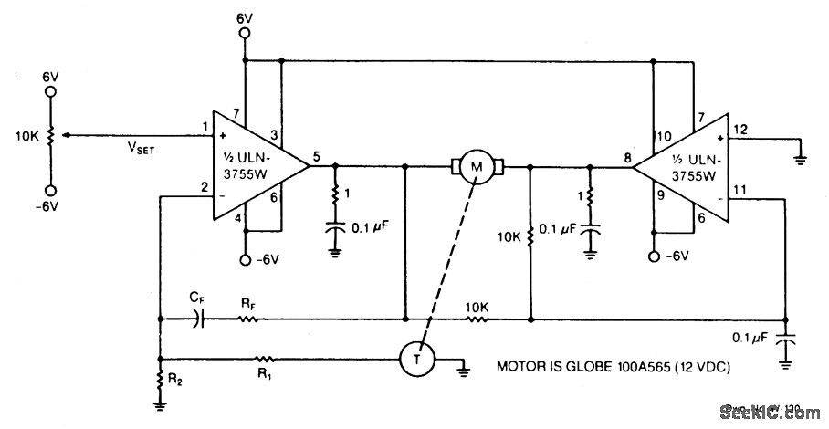
Power operational amplifiers provide precise speed control for DC motors. The circuit enables bidirectional speed control. The amplifiers' push-pull configuration guarantees a full rail-to-rail voltage swing (excluding the saturation drops of the output stages) across the motor in both...
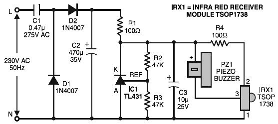
Remote control tester circuit diagram. The tester is designed around the infrared receiver module TSOP1738. The operation of the remote control is indicated by a tone from the buzzer. The circuit is sensitive and has a range of about...
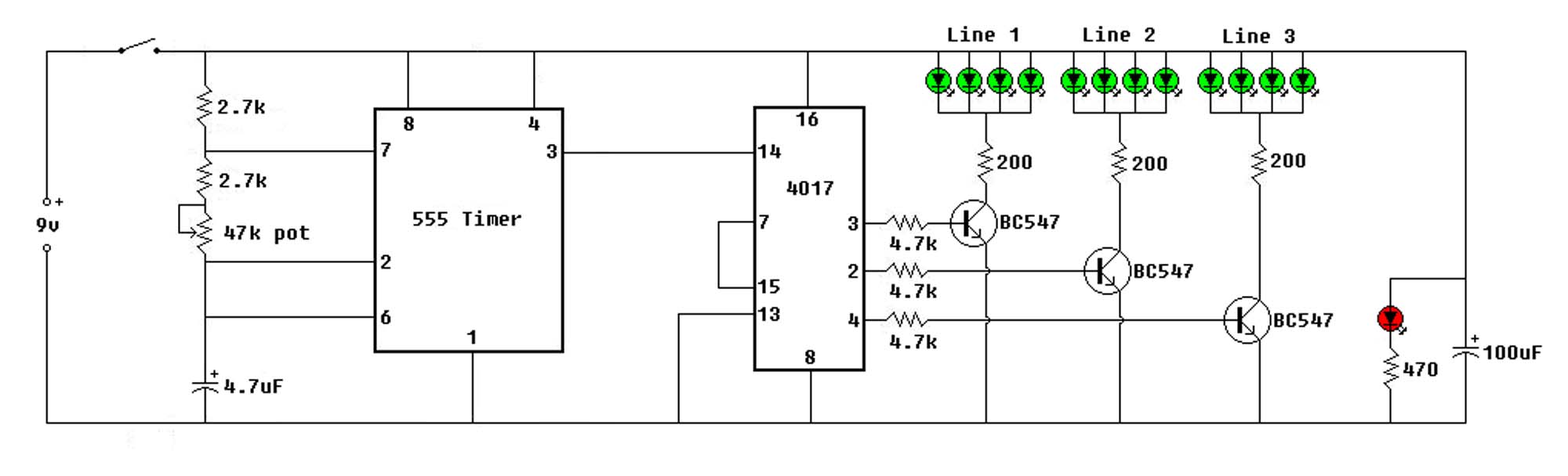
The circuit employs a 555 timer oscillator to generate clock pulses at a variable frequency, which are fed into a 4017 decade counter. The counter is configured to utilize only three outputs, while the fourth output is connected to...
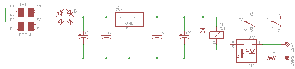
This is a common control voltage in industrial and telecommunications equipment, making relays frequently found in surplus equipment. Many relays can operate effectively on both AC and DC, providing a straightforward solution when the control voltage is switched mechanically,...
Using any camera in a dull or dark environment generally requires the use of supplementary light. This is a standard technique, and even where adequate natural light is not available, additional lighting can enhance image quality. In electronic circuit design for...
The hardware is constructed from two modules, one to capture the signal and provide timing functions, and the second as transmitter placed somewhere near the target equipment. It has been interfaced with an IBM compatible PC on the printer...