
High-Output Pulsed-Tone/Light-Activated Alarm Circuit

The circuit operates on the principle of light-dependent resistance, utilizing a Cadmium Sulfide (CDS) cell as a light sensor. The decrease in resistance of the CDS cell under illumination triggers the NOR gate configuration, which is fundamental to the operation of this audio signal generator. The output from the NOR gates produces a square wave oscillation at a frequency of 10 Hz, which serves as the modulation frequency for the subsequent oscillator stages.
The 1-kHz oscillator is composed of additional gates (c) and (d), which are configured to generate a stable tone that is pulsed in accordance with the 10-Hz modulation signal. This creates an audio output that is not only tonal but also rhythmically varied due to the low-frequency modulation.
Transistors Q1 and Q2 serve as the amplification stage of the circuit. Q1 is configured to enhance the signal from the oscillator, while Q2, specifically the 2N3055 model, is a power transistor capable of handling higher currents required to drive a speaker. This configuration allows the circuit to efficiently convert low-level audio signals into sufficient power to drive typical speakers or horns, achieving the desired output power of up to 1 W.
Overall, this circuit exemplifies a simple yet effective design for audio signal generation and amplification, leveraging light sensitivity to control the audio output while maintaining a low-frequency modulation for dynamic sound production. This circuit can produce up to 1 W of audio power to drive a speaker or horn. When the CDS cell is struck by light, its resistance decreases thus activating NOR gate (a) thereby causing (a) and (b) to produce a low-frequency (10-Hz) square wave. This pulses the 1-kHz oscillator (c) and (d), causing it to generate a pulsed 1-kHz tone at a 10-Hz rate.
Ql and Q2 amplify this signal. Q2 (2N3055) drives the speaker.
Related Circuits
This precise one-pulse-per-second clock is constructed using a few common components and is driven by a 50 or 60 Hertz mains supply, without any direct connection to it. It produces a beep or metronome-like click and/or a visible flash...
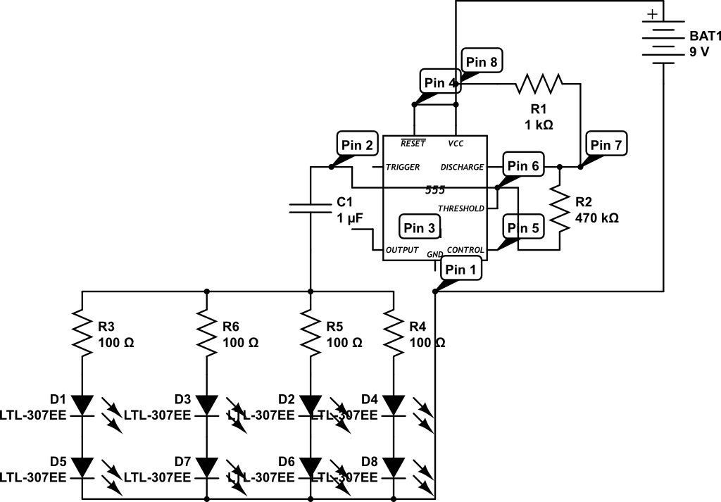
LEDs are rated for a continuous current of only 30 mA, while this circuit operates them at approximately 50 mA. Although this is acceptable for low duty cycles with short pulses, the intended design has a high duty cycle....

The ramp voltage from the low-frequency oscillator IC1 modulates IC2, thereby producing a rising and falling tone similar to the wail of police cars. The described circuit utilizes a low-frequency oscillator (IC1) to generate a ramp voltage. This ramp voltage...
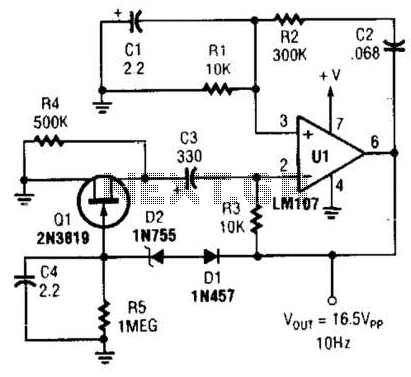
This Wien-bridge sine-wave oscillator utilizes a 2N3819 as an amplitude stabilizer. The 2N3819 functions as a variable-resistance element within the Wien bridge. The Wien-bridge oscillator is a type of electronic oscillator that generates sine waves. It employs a bridge circuit...

The objective of this project was to create a custom device utilizing local manufacturing resources. At that time, there was a pressing need for a Dub Siren. A circuit diagram was located, and with the assistance of an electronics...
Configured with capacitive coupling by inserting a small capacitor between the phototransistor and the bipolar transistor, this relay circuit will respond only to rapid changes. This relay circuit utilizes capacitive coupling to enhance its responsiveness to fast signal changes. The...