
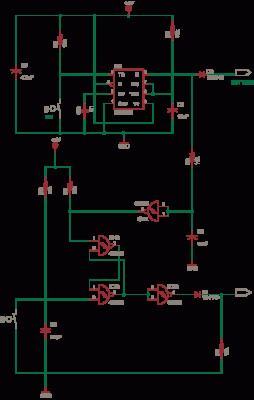
230V LED DRIVER CIRCUIT

The 230V LED driver circuit described is designed to efficiently power LEDs directly from the mains supply without the need for a bulky transformer. The circuit typically employs a rectification stage using diodes to convert the incoming AC voltage to DC. A common approach is to use a bridge rectifier configuration, which consists of four diodes arranged in a bridge formation, allowing for full-wave rectification. This ensures that the output voltage is always of the same polarity, suitable for LED operation.
Following rectification, the output voltage can be quite high and may need to be reduced to a safe operating level for the LEDs. This is often accomplished using a resistor in series with the LED array. The resistor serves to limit the current flowing through the LEDs, protecting them from overcurrent conditions which can lead to premature failure. The value of the resistor can be calculated based on the desired forward current for the LEDs and the voltage drop across the LED array.
In addition to resistors, capacitors may also be employed to smooth the output voltage after rectification, reducing ripple and providing a more stable DC supply for the LEDs. The choice of capacitor value will depend on the load characteristics and the desired level of smoothing.
It is important to note that while this transformerless approach offers advantages in terms of size and cost, it also requires careful consideration of safety standards, as the circuit is directly connected to the high-voltage mains supply. Proper insulation and protection measures must be implemented to ensure user safety and compliance with electrical regulations.
Overall, this 230V LED driver circuit represents an innovative solution for powering LEDs efficiently while minimizing component count and overall circuit dimensions.I am presenting you a 230V LED Driver circuit without transformer. Here i am using 5 led`s you can increase the count at your convineance. Due to the absence of Transformers we can reduce the cost and size of the circuit considerably. As we all know LED`s are Cheap, efficient and cool device with low power consumption. So we can reduce our el ectricity bills to a great extent. Led`s commonly works only in DC, so we have to convert the alternating current to direct current and step down to a safe value before applying to the led sequence. 🔗 External reference
Related Circuits
All devices emit intense red light with a wavelength of 660 nm. Some biophysicists suggest that light at this wavelength can positively affect the human body and initiate healing processes. This form of treatment, known as phototherapy, is claimed...

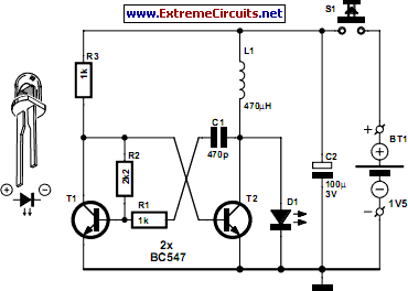
Each trigger input can produce a fixed number of pulses, with the range being from 2 to 30. The specific number is determined by the frequency-controlled settings of 1 megohm. A monostable gated unsteady power supply circuit can be...
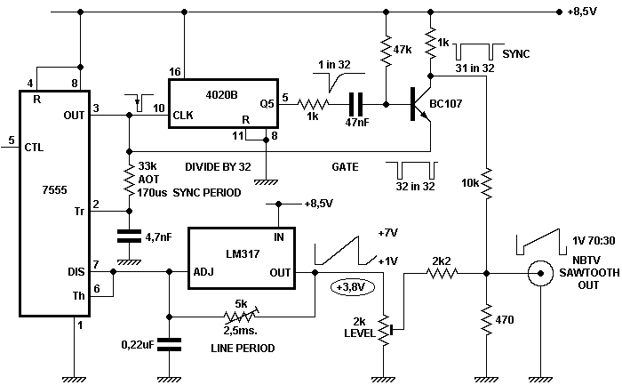
To achieve optimal performance from an NBTV signal, it is crucial to utilize the complete dynamic range of the signal without any crushing at the black level or peak white. To evaluate the linearity of a video path, it...
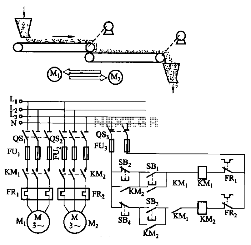
The circuit depicted in Figure 3-86 utilizes a line utilization time relay to control two motors, starting one before the other after an initial stall. The time relay KTi can be adjusted to modify the starting interval of the...
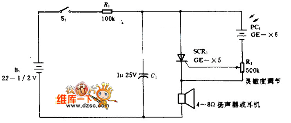
In the silicon-controlled trigger circuit, a cadmium sulfide cell is connected to a relaxation oscillator, which serves as a sensor to activate a blinking light in a darkroom. This setup causes a speaker to emit a warning sound of...
This circuit is a simple -5V power supply using a 555 timer, designed for low-power analog applications involving FET operational amplifiers. The circuit converts +5V to -5V to create a dual power supply. It operates as a 555 astable...