
Sawtooth generator circuit
The described NBTV sawtooth generator circuit is a sophisticated design that effectively produces a linear sawtooth waveform essential for generating test signals in narrow-band television systems. The choice of components, such as the 7555 timer and LM317 voltage regulator, ensures stability and precision in the output signal. The 7555 timer functions as the heart of the sawtooth generator, where its timing characteristics are carefully adjusted to create a linear ramp voltage. The use of two timing capacitors allows for fine-tuning of the active line time and line sync duration, ensuring that the output signal conforms to the required specifications for NBTV.
The LM317 regulator's role as a constant current source is critical for achieving a linear charge on the timing capacitor, which is vital for maintaining the integrity of the sawtooth waveform. Its low output impedance further enhances the performance by minimizing signal distortion, which is particularly important for video signals where fidelity is paramount.
The 4020 binary counter's implementation as a divide-by-32 mechanism allows for precise generation of the required line sync pulses, which are essential for synchronizing the video signal. The grounded base transistor configuration effectively differentiates the signal, ensuring that only the necessary sync pulses are produced. This selective gating process contributes to a clean and well-defined output signal.
Finally, the mixing of the attenuated sawtooth waveform with the 31 sync pulses results in a standardized NBTV signal characterized by a 70%-30% duty cycle at 1 V output. This configuration is particularly suited for applications in narrow-band television, where signal integrity and adherence to standards are critical. The output impedance of 470 ohms is also a standard value that facilitates compatibility with various video equipment, ensuring that the generator can be easily integrated into existing systems.To get the best from an NBTV signal it is important to use the full dynamic range of the signal with no crushing at black level or peak white. To check the linearity of a video path it is usual to use either a staircase or sawtooth test signal.
The circuit described is a free standing NBTV sawtooth generator conforming to the standard of 1volt output level and complete with 31 line sync pulses. The 7555 timer and LM317 regulator form a linear sawtooth generator. Two timing capacitors are employed, one setting the active line time which may be trimmed by the pot, the second sets the line sync duration. The circuit is un-usual in that the LM317 performs two roles. It acts as constant current genera-tor to linearly charge the 0. 22 mF capacitor, and also provides a very low output impedance. The 4020 counter is used as a divide-by-32 fed from line pulses. The grounded base transistor differentiates the falling edge from Q5 of the 4020 and gates out one sync pulse in 32, the output from the gate being non-inverting.
The remaining 31 sync pulses are mixed with an attenuated sawtooth to form a standard 70%-30% 1 V NBTV signal and delivered at a nominal 470 © impedance. 🔗 External reference
Related Circuits
This pulse generator utilizes a single integrated circuit (IC) and six passive components to achieve a frequency range of 400 to 4000 Hz, with an adjustable duty cycle ranging from 1% to 99%. The circuit employs a threshold detector...

Voltage variations and power cuts adversely affect various equipment such as TVs, VCRs, music systems, and refrigerators. This simple circuit will protect costly equipment from high and low voltages and voltage surges when power resumes. It also produces a...

This simple circuit can monitor the overflow of water from the overhead tank. The sensor placed close to the lid of the overhead tank continuously monitors the presence of water. The described circuit functions as a water overflow monitoring system...
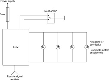
A central door locking system allows all doors, including the boot lid or tailgate, to be locked centrally from the driver's door, typically including the front passenger's door as well. The locking and unlocking actions are performed by an...
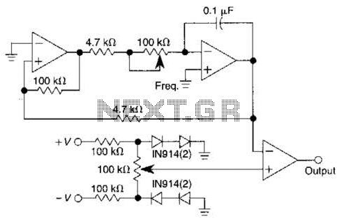
This scan is from an old ETI Circuits #2 publication from the 1970s. It contains valuable operational amplifier information that is highly useful. With some knowledge, the six circuits presented serve as an instant reference, enabling various applications. These...
The BLW96 is a high-frequency (HF) and very high-frequency (VHF) power transistor designed for use in class A, AB, and B operated high-power industrial and military transmitting equipment. The BLW96 transistor is a crucial component in RF (radio frequency) applications,...
Warning: include(partials/cookie-banner.php): Failed to open stream: Permission denied in /var/www/html/nextgr/view-circuit.php on line 713
Warning: include(): Failed opening 'partials/cookie-banner.php' for inclusion (include_path='.:/usr/share/php') in /var/www/html/nextgr/view-circuit.php on line 713