
Belt conveyor interlock motor operation sequence control circuit

The circuit operates by employing a time relay system that ensures a sequential start of two electric motors, preventing potential overloads or mechanical stress that could occur if both motors were to start simultaneously. The time relay KTi is crucial for setting the delay time before the second motor is activated after the first motor has been started. This adjustment is essential for applications where staggered motor operation is required to manage load conditions effectively.
Furthermore, the second time relay, KT2, provides an adjustable downtime interval between the operations of the motors. This feature is particularly useful in applications where the motors are not required to run continuously and need to be cycled on and off at specific intervals. The ability to fine-tune both the start and downtime intervals enhances the flexibility of the circuit, allowing it to be tailored to the specific operational needs of the machinery involved.
The circuit should include proper protection mechanisms, such as fuses or circuit breakers, to safeguard against potential electrical faults. Additionally, the relay contacts should be rated appropriately to handle the load of the motors being controlled. Proper wiring and layout considerations must also be taken into account to minimize electromagnetic interference and ensure reliable operation.
Overall, this time relay-controlled motor circuit is suitable for various industrial applications, providing an efficient solution for managing motor operations with adjustable timing features. Circuit shown in Figure 3-86. The line utilization time relay to control two motors, one of the first than the other after starting stall. Adjust the time relay KTi, two electr ic motors can change the interval start; adjust KT2, two Taipower can change the interval motivation downtime.
Related Circuits
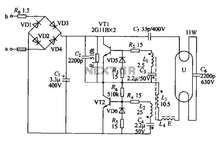
Energy-saving lamps are categorized into self-ballasted compact types and single-ended structures. They can also be classified based on appearance into various forms such as double-tube, four-tube, six-tube types, and others. The lifespan of energy-saving lamps is approximately ten times...
This precise one-pulse-per-second clock is constructed using a few common components and is powered by a 50 or 60 Hertz mains supply without any direct connection to it. A beep or metronome-like click, along with a visible flash, indicates...
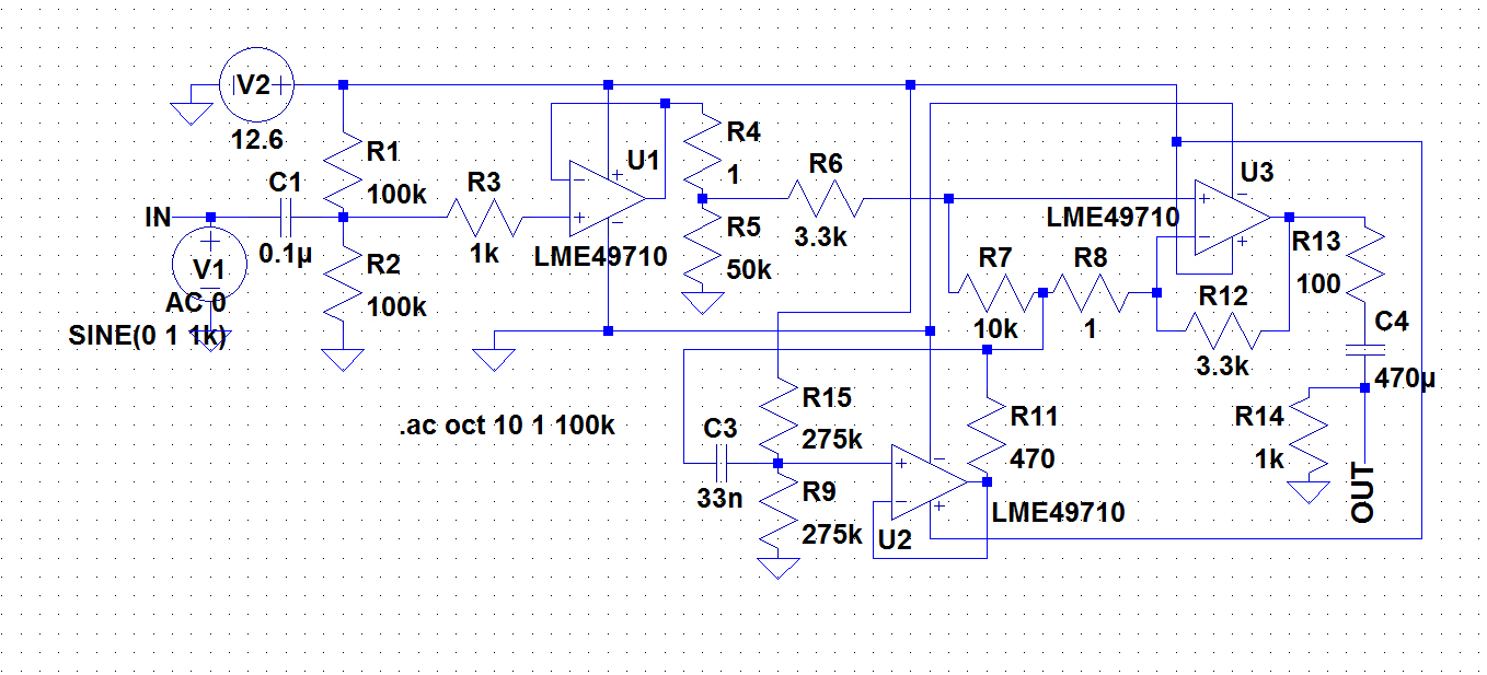
A circuit was required to function as a bass boost. The design was adapted from a circuit by ESP Sound, focusing solely on the frequency range of 35-150 Hz. The bass boost circuit, as adapted from the original design, primarily...
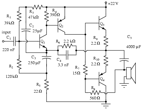
Note that Q3 and Q4 in the figure below are complementary, with Q3 being an NPN transistor and Q4 being a PNP transistor. This circuit is suitable for moderate power audio amplifiers. For a detailed explanation of this circuit,...

This page features a circuit that has twenty open collector outputs that turn on one at a time in a continuous sequential manner. The circuit utilizes the 74LSxx family of TTL integrated logic devices. The circuits are designed to...
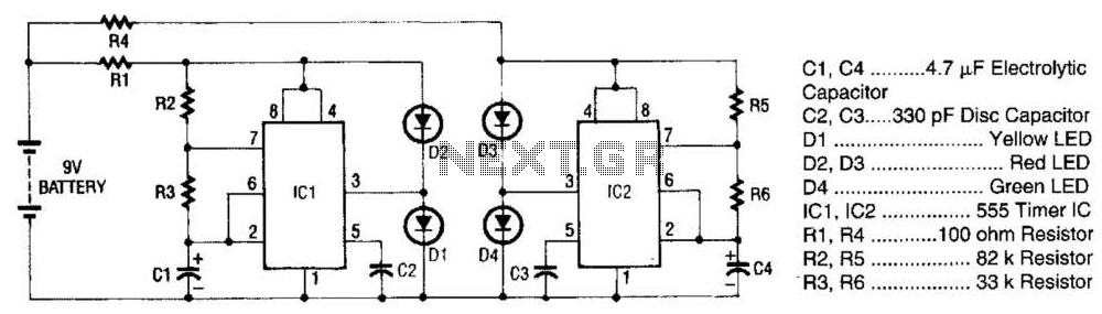
The super LED flasher consists of two complete LED flasher circuits integrated onto a single circuit board. The first LED flasher is comprised of IC1 and LEDs D1 and D2. IC1 is a 555 timer IC configured as an...