
24V to 36V Battery Charger Circuit

The 24V to 36V linear battery charger is designed to provide a stable charging voltage suitable for higher voltage lead-acid batteries. The circuit employs a linear regulation method, which, despite being an older technique, offers advantages such as simplicity and reliability.
The charger typically comprises a transformer, rectifier, filter capacitors, and a linear voltage regulator. The transformer steps down the input AC voltage to a lower AC voltage suitable for charging. The rectifier, usually a bridge rectifier configuration, converts the AC voltage to DC. Filter capacitors smooth out the rectified voltage to minimize ripple, ensuring a steady DC output.
The linear voltage regulator is the core component that maintains the output voltage within the specified range of 24V to 36V. It operates by dissipating excess voltage as heat, which necessitates the use of a heat sink to prevent overheating during operation. The output voltage can be adjusted using a feedback mechanism, allowing for precise control over the charging process.
Additionally, incorporating protection mechanisms such as over-voltage, over-current, and thermal shutdown features is essential to safeguard both the charger and the battery being charged. These safety features help prevent damage due to incorrect voltage levels or excessive current flow, which can lead to battery degradation or failure.
Overall, this linear battery charger design is suitable for applications requiring reliable and efficient charging of higher voltage lead-acid batteries, making it a valuable solution in various electronic and automotive applications.This 24V to 36V linear battery charger is long overdue. While this is an old circuit technique, it is optimized for charging higher voltage lead-acid batte.. 🔗 External reference
Related Circuits
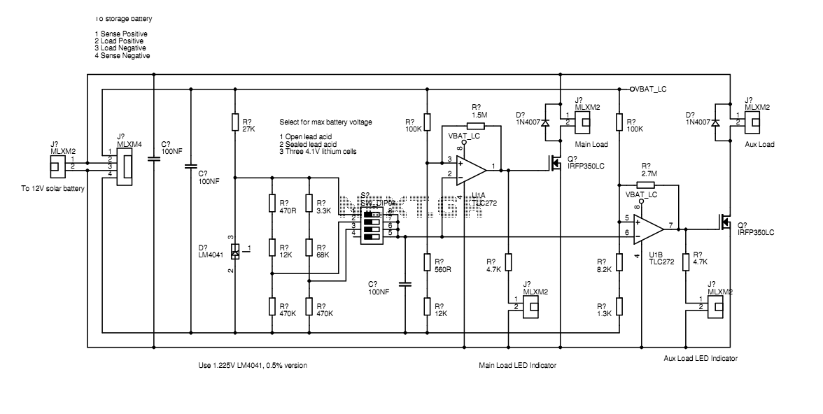
In the actual device the transistors are bolted to the aluminium case. The schematic diagram shown here represents how the circuit would be built if all components were on-board. Separate paths for load current and voltage sensing allow the...
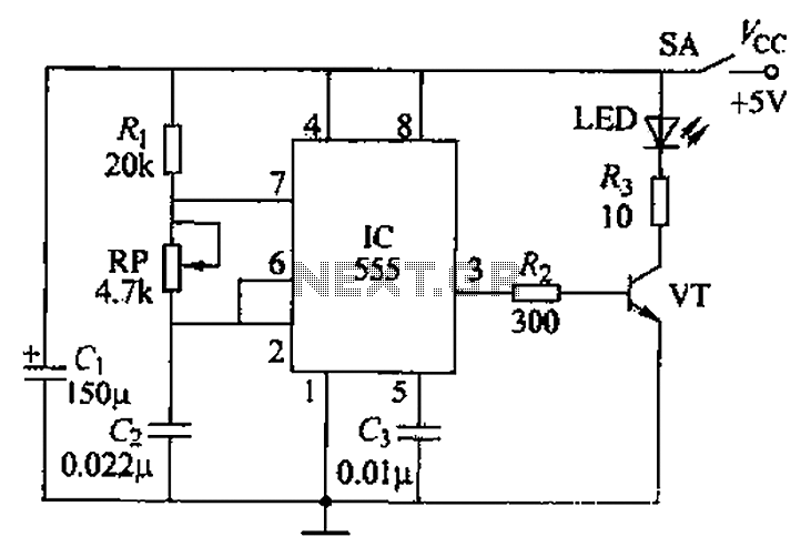
The circuit utilizes a 555 timer integrated circuit along with a transistor (VT) and several external components to create a multivibrator circuit. The charge and discharge time constants, Ti and T2, are defined, where Ti is approximately 0.7 times...

A pH electrode measures hydrogen ion (H+) activity and generates an electrical potential or voltage. The operation of the pH electrode is based on the principle that an electric potential develops when two liquids of different pH come into...
The circuit is a temperature-to-pulse-width converter. The LM3524 is used to convert the output of an LM135 temperature transducer into a pulse width that can be measured by a digital system, such as a microprocessor-controlled data acquisition system. In...
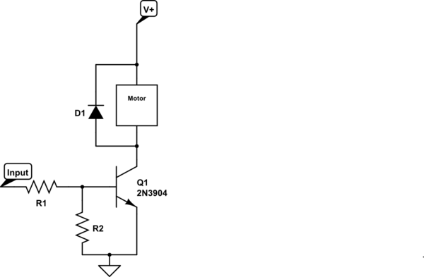
Control a small 5V motor using an external power supply by triggering a transistor with an Arduino. The transistor in use is an NPN type, specifically the 2N3904. To control a small 5V motor using an Arduino and an NPN...
A controllable gain amplifier functions as an automatic gain control circuit within the execution unit. The primary methods for controlling the amplifier's gain involve two approaches: one is by adjusting certain parameters of the amplifier itself, such as emitter...