
Temperature To Pulse Width Converter Circuit Using LM3524

The temperature-to-pulse-width converter circuit operates by utilizing the linear voltage output of the LM135 temperature sensor, which provides a voltage that varies with temperature. This voltage is fed into the operational amplifier (A1), configured to amplify the signal to a suitable level for the LM3524. The LM3524 is a versatile PWM controller that generates output pulses whose width is proportional to the input voltage, allowing for precise temperature measurement and control.
The circuit's feedback mechanism plays a crucial role in maintaining linearity in the output pulse width. By integrating the output of the LM3524 and feeding it back to the negative input of A1, the circuit stabilizes the output pulse width against fluctuations in temperature, ensuring accurate readings. The gain trim potentiometer allows for fine-tuning of the output, accommodating variations in component tolerances and ensuring that the pulse width corresponds accurately to the temperature range of interest.
The inclusion of a 1000 pF capacitor aids in loop stability by compensating for phase shifts that may occur in the feedback loop, thus preventing oscillations that could lead to inaccurate pulse width outputs. Additionally, the LM358 operational amplifier's ability to operate with input voltages close to ground enhances the circuit's sensitivity, allowing it to detect small changes in temperature effectively.
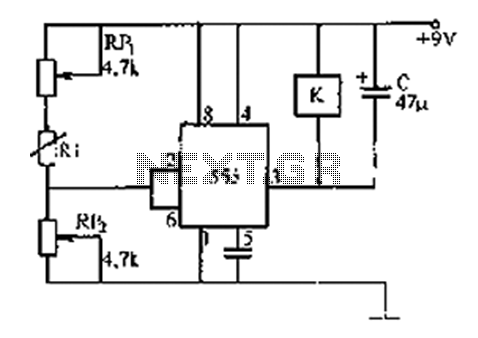
The output from pin 3 of the LM3524 serves a dual purpose; it provides a pulse that can trigger digital counters or microcontroller inputs, facilitating the integration of the temperature sensing circuit with digital systems for data logging or control applications. The overall design of this circuit exemplifies a well-thought-out approach to converting temperature readings into a format suitable for digital processing, enabling efficient and accurate temperature monitoring and control.The circuit is temperature to pulse width converter. The LM3524 to convert the output of an LM135 temperature transducer into a pulse width which can be measured by a digital system, such as a microprocessor controlled data acquisition system. In this circuit, the LM135`s temperature-dependent output (10 mV/ °K) is divided down and applied to A1`s
positive input. This moves A1`s output high, driving the input to the LM3524`s pulse width modulation circuitry. The LM3524 pulse-width output is clipped by the LM185 reference and integrated by the 1 MW-0. 1 µF combination. The DC level across the 0. 1 µF capacitor is fed back to A1`s negative input. This feedback path forces the LM3524`s output pulse width to vary in a highly linear fashion according to the potential at A1`s positive input. Here is a schematic drawing: The overall temperature to pulse width scale factor is adjusted with the gain trim potentiometer.
The 1000 pF capacitor provides stable loop compensation. A1, an LM358, allows voltages very close to ground to be sensed. This provides greater input range than the LM3524`s input amplifier, which has a common mode range of 1. 8 3. 4V. The oscillator output pulse at pin 3 may be used to reset counters or other digital circuitry because it occurs just before the output pulse width begins.
🔗 External reference
Related Circuits
The 555 timer integrates both analog and digital functions within a scaled integrated device. Typically manufactured using a bipolar process, it is designated as the 555 timer, while the CMOS version is referred to as the 7555. In addition...
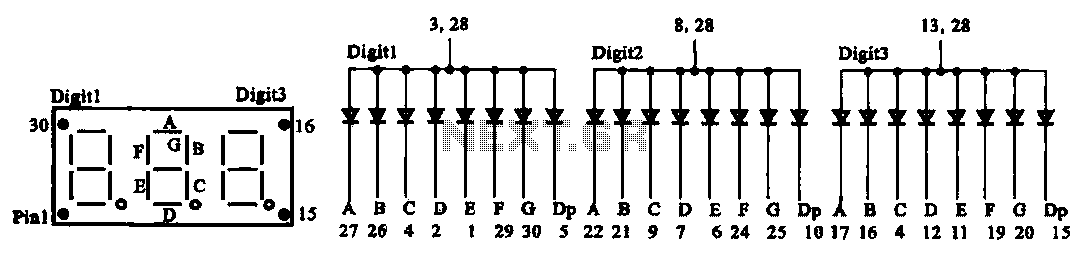
The document presents two types of digital display circuits. The first type (a) utilizes a common anode circuit configuration, while the second type (b) employs a common cathode circuit structure. The common anode display circuit configuration consists of multiple light-emitting...

This power converter is utilized in the LHC machine to supply power to superconducting magnets. It is situated within the underground installation of the LHC, positioned close to the loads to minimize cable losses. The converter operates at a...
Power pulse circuit using LM350 and NE555. This circuit can be used to drive lamps, power LEDs, DC motors, etc. Adjust R5 for output amplitude and R1 for output power. The LM350 is an adjustable 3-terminal voltage regulator. The power...
The output frequency can be altered based on the division ratio of the comparison frequency in the 10 kHz unit, with the division ratio set to 1024 in this circuit. Given that the amateur radio bandwidth in Japan is...

This circuit is designed for general-purpose use with a large LED display utilizing SPI serial interfacing. It employs a serial-in-parallel-out shift register, specifically the 74HC595, to receive serial data from a microcontroller board. The schematic wiring indicates that SER...