
ph electrode circuit

The pH measurement circuit described utilizes a pH electrode, which is a specialized sensor designed to detect the activity of hydrogen ions in a solution. The electrode comprises a glass membrane that selectively interacts with H+ ions, producing a voltage proportional to the pH level of the solution. This voltage is typically bipolar, oscillating around zero volts, which poses challenges for interfacing with single-supply systems.
The design incorporates an operational amplifier (U1) configured to offset the pH signal by introducing a stable bias of 512 mV. This offset is generated using the LM4140A-1.0 voltage reference, which ensures precision and stability in the output voltage. The resistor divider network, consisting of two 10 kΩ resistors, effectively halves the reference voltage to achieve the desired offset.
The output of U1 is connected to the reference electrode of the pH sensor, allowing the sensor to operate with a bias that shifts its output range. This is critical in applications where the measurement system is powered by a single supply, as it ensures that the signal remains within the acceptable voltage range for further processing.
The second operational amplifier (U2) serves as a buffer, configured again in a unity-gain mode. This configuration is essential for maintaining high input impedance, which minimizes loading effects on the pH electrode. By buffering the output, the circuit enhances compatibility with various measurement instruments, particularly those with lower input impedance that might otherwise distort the signal.
The design allows for flexibility in applications where the output voltage from the pH electrode may need to be amplified. If required, additional gain can be introduced by integrating external resistors into the feedback loop of U2, thereby tailoring the output signal to meet specific measurement requirements.
Overall, this circuit design effectively addresses the challenges associated with measuring pH levels in various solutions, ensuring accurate and reliable readings while maintaining compatibility with a range of instrumentation.A pH electrode measures hydrogen ion (H+) activity and produces an electrical potential or voltage. The operation of the pH electrode is based on the principle that an electric potential develops when two liquids of different pH come into contact at opposite sides of a thin glass membrane. This is a design circuit for the measurement. This is the figure of the circuit. Amplifier U1 off sets the pH electrode by 512 mV. This is achieved by using National`s LM4140A-1. 0 precision micro power low-dropout voltage reference that produces an accurate 1. 024V. That voltage is divided in half to equal 512 mV by the 10 k © resistor divider. The output of amplifier U1, which is set up in a unity-gain configuration, biases the reference electrode of the pH electrode with the same voltage, 512 mV, at low impedance. The pH-measuring electrode will produce a voltage which rides on top of this 512 mV bias voltage. In effect, the circuit shifts the bipolar pH-electrode signal to a uni-polar signal for use in a single-supply system.
The second amplifier U2 is set up in a unity-gain configuration and buffers the output of the pH electrode. Again, a high-input impedance buffer between the pH electrode and the measurement instrument allows the circuit to interface with a greater variety of measurement instruments including those with lower input impedance.
In most applications, the output voltage of the pH electrode is high enough to use without additional amplification. If amplification is required, this circuit can easily be modified by adding gain resistors to U2. 🔗 External reference
Related Circuits
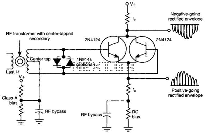
This amplifying full-wave detector circuit is simple yet sensitive, featuring an almost zero rectification threshold. It provides a highly linear RF load to the final IF stage. The gain for the collector output is approximately given by r jre,...
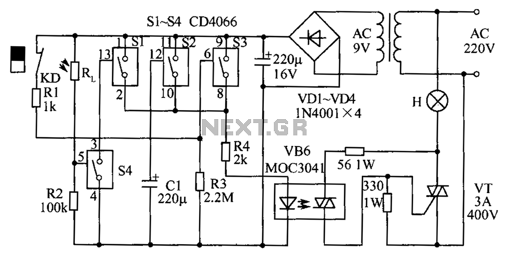
The circuit diagram illustrates a group of four analog electronic circuit switches (S1 to S4). Switches S1, S2, and S3 are utilized in a parallel delay circuit. When the power is activated, resistor R4 drives the triac VT, which...
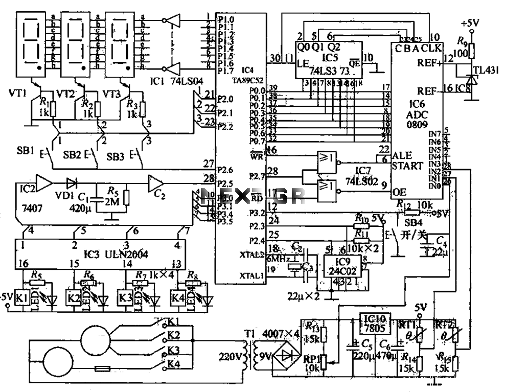
The circuit functions as a computer logo-conditioned temperature control system as depicted in Figure 1-58. The primary component is the AT89C52 microcontroller. When powered on, the 4C02 microcontroller first retrieves the last saved setpoint temperature and the operational state...
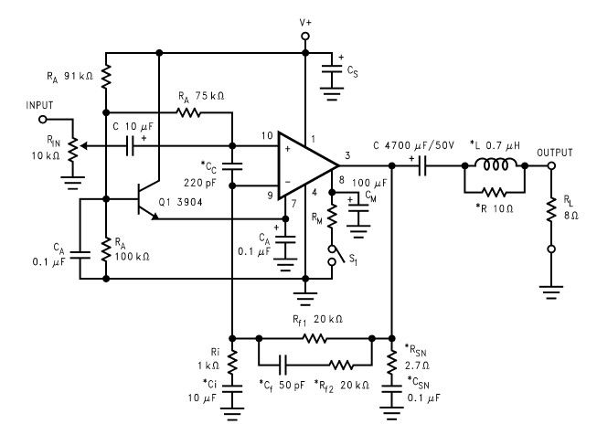
The LM2876 audio power amplifier circuit can be designed as a simple, high-efficiency audio amplifier capable of delivering 40W of continuous average power to an 8-ohm load with a total harmonic distortion plus noise (THD+N) of 0.1% from 20Hz...
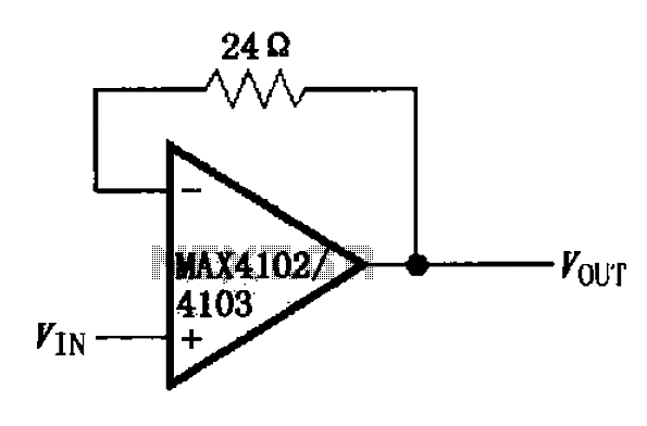
The MAX4102/4103 unity gain buffer circuit is illustrated in the figure. This circuit incorporates a small resistor (24 ohms) positioned in the feedback loop of the amplifier, which forms a unity gain buffer. Additionally, it achieves a maximum bandwidth...
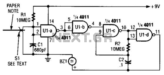
This device prevents paper notes and memos from being overlooked. A paper note placed between two fingers made of a conducting material (metal or conductive plastic) breaks the circuit, allowing pair 1 of Ul-a to go high. This causes...