
25 kHz Ultrasound Transducer

To design an ultrasound transmitter and receiver circuit operating at 25 kHz, the following components and configurations are recommended:
**Transmitter Circuit:**
1. **Oscillator**: A 25 kHz signal can be generated using a 555 timer IC configured in astable mode. The frequency can be set by choosing appropriate resistor and capacitor values (for example, R1 = 1.5 kΩ, R2 = 10 kΩ, and C1 = 10 µF).
2. **Amplifier**: The output from the 555 timer can be fed into a transistor amplifier (such as a NPN transistor) to increase the power of the signal. The transistor should be connected in a common-emitter configuration to boost the output drive capability.
3. **Transducer**: A suitable ultrasonic transducer should be connected to the output of the amplifier. The transducer converts the electrical signal into ultrasonic sound waves. The specifications of the transducer should match the operating frequency of 25 kHz.
4. **Power Supply**: Ensure that the circuit is powered by a stable DC power supply, typically between 5V to 12V, depending on the specifications of the components used.
**Receiver Circuit:**
1. **Transducer**: An ultrasonic transducer that operates at 25 kHz should also be used for receiving the ultrasonic signals. The transducer will convert the incoming ultrasonic waves back into electrical signals.
2. **Amplifier**: The received signal will be weak and should be amplified using an operational amplifier (op-amp) configured in a non-inverting mode. This will help in boosting the signal for further processing.
3. **Bandpass Filter**: A bandpass filter can be implemented to isolate the desired 25 kHz signal from ambient noise. This can be achieved using a combination of capacitors and inductors or using active filtering techniques with op-amps.
4. **Demodulator**: If the transmitted signal is modulated, a demodulator circuit will be necessary to extract the original signal. This can be done using envelope detection or synchronous detection methods.
5. **Output**: The output of the receiver circuit can be connected to a microcontroller or an analog-to-digital converter (ADC) for further processing and analysis of the received signal.
**Considerations**:
- Proper grounding and shielding should be implemented to minimize interference and noise in both circuits.
- Testing and calibration of the circuits are essential to ensure accurate transmission and reception of ultrasonic signals.
- The layout of the circuit on a PCB should consider the placement of components to reduce parasitic capacitance and inductance, which can affect performance at high frequencies.
This comprehensive approach will facilitate the successful development of the transmitter and receiver circuits for ultrasound applications at the specified frequency.I am trying to create two circuits * 1 transmitter * 1 receiver for ultrasounds. I all ready have a pair of 25 kHz transmitter/receiver.. 🔗 External reference
Related Circuits
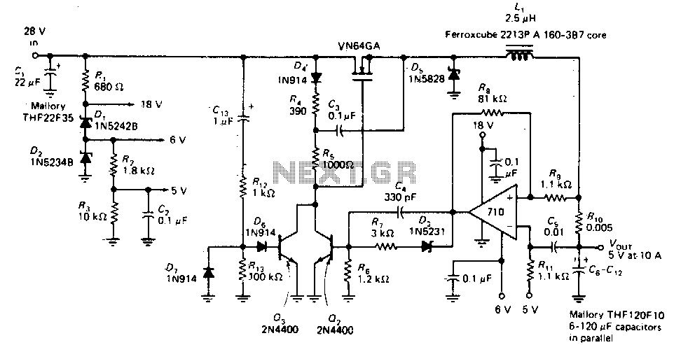
This circuit provides a regulated DC output with less than 100 mV of ripple for microprocessor applications. The required operating voltages are derived from a bleeder resistor network connected across the unregulated 28 V supply. The output of the...
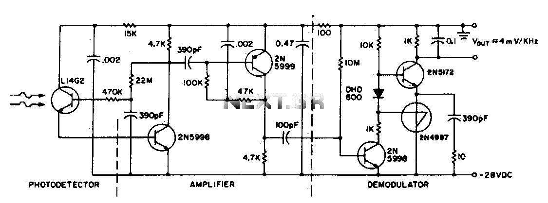
This circuit consists of an L14G2 detector, two stages of gain, and an FM demodulator. Better sensitivity can be obtained using more stages of stabilized gain with automatic gain control (AGC). The circuit design features an L14G2 detector, which serves...
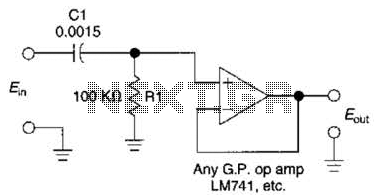
This simple 1 kHz filter utilizes a voltage follower and an RC section as its filtering element. For other frequencies, the -3 dB point is given by the formula 1/(6.28 Rl Cv), and the response decreases at a rate...
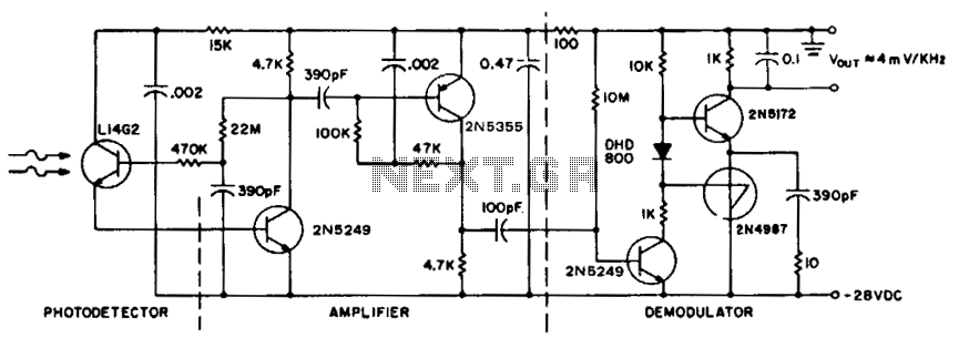
To achieve maximum range, the receiver should be constructed similarly to a radio receiver front end, as the signals received will exhibit comparable frequency components and amplitudes of the photodiode current. The primary limitation on the receiver's performance is...
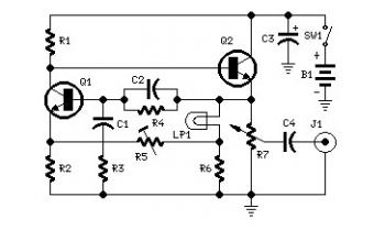
Set R5 to read 1V RMS on an audio millivoltmeter connected to the output with R7 rotated fully clockwise, or to view a sine wave of 2.828V peak-to-peak amplitude on the oscilloscope. An audio amplifier is an electronic device...
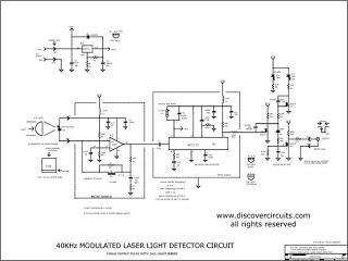
This circuit was originally designed to detect weak flashes of laser light reflected off a fabric video projection screen. It was utilized as part of a firearm training system. The circuit generates a 100 ms output pulse whenever it...