
25 Watt MosFet Amplifier

This circuit describes a high-quality audio amplifier design that emphasizes simplicity and direct connectivity to various audio sources. The absence of a preamplifier allows for a streamlined approach, making it suitable for direct connection to devices such as CD players, tuners, and tape recorders.
The circuit incorporates a 10K logarithmic potentiometer, which is configured as a dual-gang component for stereo applications. This potentiometer serves as a volume control, enabling the user to adjust the audio output level conveniently. Additionally, a switch is included to manage multiple audio sources, ensuring versatility in the circuit's operation.
The design specifies the use of transistors Q6 and Q7, which require a small U-shaped heatsink to dissipate heat effectively during operation. This is critical for maintaining performance and reliability. Similarly, transistors Q8 and Q9 are also mounted on heatsinks to enhance thermal management, which is vital for preventing thermal runaway and ensuring consistent operation.
An important aspect of the circuit is the adjustment of resistor R11, which is used to set the quiescent current at 100mA. This adjustment is crucial for optimizing the performance of the amplifier, and it is recommended to measure the current using an Avo-meter connected in series with the drain of Q8. This procedure should be performed when there is no input signal present, ensuring accurate measurement without interference from audio signals.
Proper grounding is emphasized as an essential element of the circuit design. Effective grounding minimizes noise and interference, which is particularly important in audio applications where signal integrity is paramount.
Overall, this circuit design presents a practical solution for audio amplification, combining simplicity with effective thermal management and flexibility in audio source handling.High Quality simple design No need for a preamplifier Can be directly connected to CD players, tuners and tape recorders. Simply add a 10K Log potentiometer (dual gang for stereo) and a switch to cope with the various sources you need.
# Q6 & Q7 must have a small U-shaped heatsink. # Q8 & Q9 must be mounted on heatsink. # Adjust R11 to set quiescent current at 100mA (best measured with an Avo-meter connected in series to Q8 Drain) with no input signal. # A correct grounding i 🔗 External reference
Related Circuits
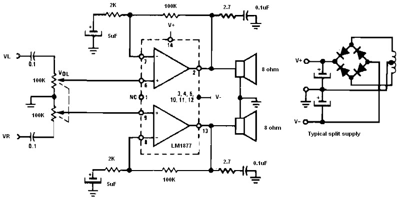
Non-inverting audio amplifier schematic. This non-inverting audio amplifier circuit can be utilized in multi-channel audio systems, stereo phonographs, tape recorders and players, AM-FM radio receivers, servo amplifiers, intercom systems, and automotive products. The audio amplifier described here employs two...
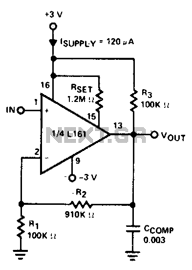
The amplifier is 3 dB down at 100 kHz and has a slew rate of 0.02 V/µs. The amplifier's performance characteristics indicate that it experiences a 3 dB attenuation at a frequency of 100 kHz. This specification suggests that at...
This circuit demonstrates that dimmers designed for mains voltage do not necessarily require a triac. Instead, a MOSFET (BUZ41A, 500 V/4.5 A) is utilized within a diode bridge to manage the voltage across an incandescent bulb using pulse-width modulation...
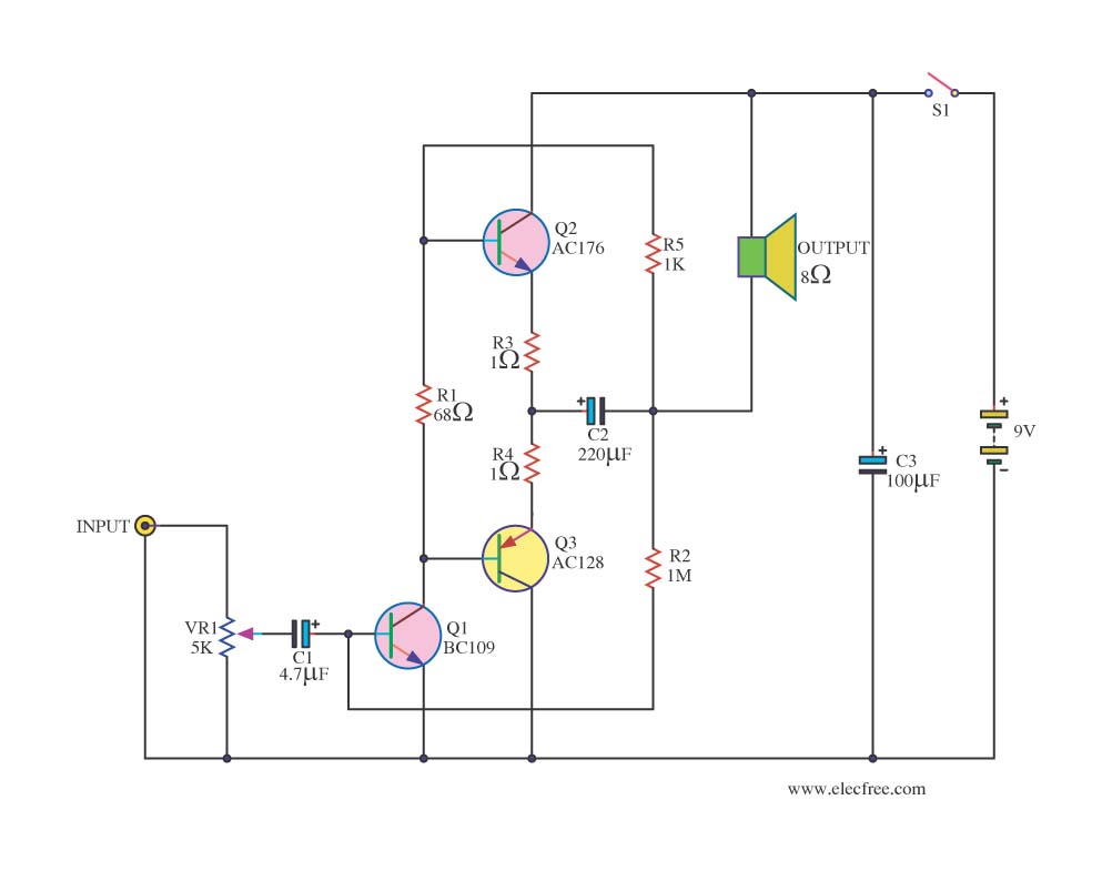
Integrated circuits (ICs) are commonly utilized in various audio amplifiers, particularly in compact circuits. While transistors are convenient alternatives, they offer several advantages, such as the ability to repurpose old equipment to create smaller circuits, which may be harder...
The operational amplifier (op-amp) has a significant history, particularly with the 741/301 series, which has been popular for approximately 20 years due to its ease of calculation (gain calculation), affordability, and simplicity of construction. The versatility of op-amps allows...
The ability amplifier has remained functional since it was first introduced in 2002. It is not broken, so there is no reason to fix it. The accompanying photo shows a well-assembled board (known as M27). Utilizing TIP35/36C transistors, the...