
Dimmer With A MOSFET

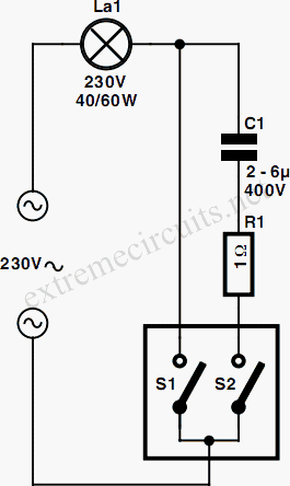
The described circuit utilizes a MOSFET-based dimming solution that effectively manages incandescent bulb brightness by adjusting the voltage through PWM techniques. The MOSFET (BUZ41A) is a crucial component, acting as a switch in the circuit, allowing for efficient control of the power delivered to the load. The diode bridge configuration serves to rectify the AC signal, providing a DC voltage to the control circuitry.
The PWM controller is essential for modulating the power to the load. By varying the duty cycle, the average power delivered to the incandescent bulb can be adjusted, allowing for smooth dimming capabilities. The choice of components, such as the optocoupler (CNY65), enhances safety by providing electrical isolation between the high voltage and low voltage sections of the circuit.
The current limiting resistor (R5) and the rectifying diode (D6) are critical in managing the current flow, preventing excessive current that could damage the components. The capacitor (C2) helps in smoothing the rectified voltage, ensuring stable operation of the circuit.
The design considerations for resistors R3 and R4 emphasize the importance of balancing power consumption and voltage ratings. The series configuration of these resistors is a prudent choice for maintaining reliability under varying operational conditions.
Overall, this circuit exemplifies a robust and efficient approach to dimming incandescent lighting while ensuring safety and reliability through careful component selection and configuration.This circuit shows that dimmers intended for use at mains voltage do not always have to contain a triac. Here, a MOSFET (BUZ41A, 500 V/4. 5A) in a diode bridge is used to control the voltage across an incandescent bulb with pulse-width modulation (PWM).
A useful PWM controller can be found elsewhere in this issue. The power supply voltage for drivi ng the gate is supplied by the voltage across the MOSFET. D6, R5 and C2 form a rectifier. R5 limits the current pulses through D6 to about 1. 5 A (as a consequence it is no longer a pure peak rectifier). The voltage across C2 is regulated to a maximum value of 10 V by R3, R4, C1 and D1. An optocoupler and resistor (R2) are used for driving the gate. R1 is intended as protection for the LED in the optocoupler. R1 also functions as a normal current limiting device so that a hard` voltage can be applied safely. The optocoupler is anold acquaintance, the CNY65, which provides class-II isolation. This ensures the safety of the regulator. The transistor in the optocoupler is connected to the positive power supply so that T1 can be brought into conduction as quickly as possible. In order to reduce switching spikes as a consequence of parasitic inductance, the value of R2 has been selected to be not too low: 22 k is a compromise between inductive voltages and switching loss when going into and out of conduction.
An additional effect is that T1 will conduct a little longer than what may be expected from the PWM signal only. When the voltage across T1 reduces, the voltage across D1 remains equal to 10 V up to a duty cycle of 88 %.
A higher duty cycle results in a lower voltage. At 94 % the voltage of 4. 8 V proved to be just enough to cause T1 to conduct sufficiently. This value may be considered the maximum duty cycle. At this value the transistor is just about 100 % in conduction. At 230 V mains voltage, the voltage across the lamp is only 2. 5 V lower, measured with a 100-W lamp. Just to be clear, note that this circuit cannot be used to control inductive loads. T1 is switched asynchronously with the mains frequency and this can cause DC current to flow. Electronic lamps, such as the PL types, cannot be dimmed with this circuit either. These lamps use a rectifier and internally they actually operate off DC. A few remarks about the size of R3 and R4. This is a compromise between the lowest possible current consumption (when the lamp is off) and the highest possible duty cycle that is allowed. When the duty cycle is zero, the voltage across the resistors is at maximum, around 128 V with a mains voltage of 230 V.
Because (depending on the actual resistor) the voltage rating of the resistor may be less than 300 V, two resistors are connected in series. The power that each resistor dissipates amounts to a maximum of 0. 5 W. With an eye on the life expectancy, it would be wise to use two 1-W rated resistors here. 🔗 External reference
Related Circuits
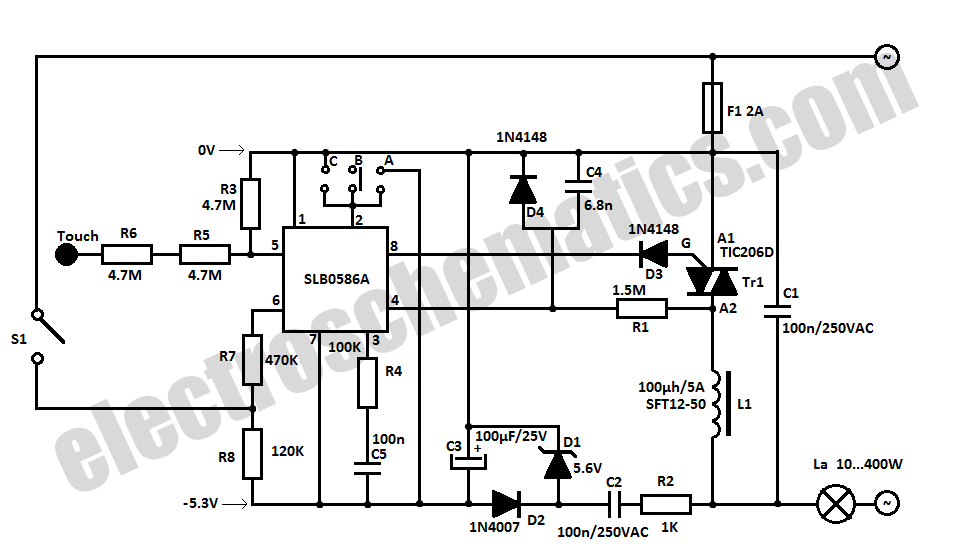
The SLB0586A integrated circuit from Siemens can be utilized to create a simple touch light dimmer circuit, allowing for the adjustment of lamp intensity. When paired with a TIC206D triac, this setup enables smooth regulation of light intensity for...
This electronic lighting dimmer circuit is designed to control the brightness of incandescent lamps, but it is not suitable for fluorescent lamps. It operates with both 110V and 220V AC power sources. The circuit is connected in series with...
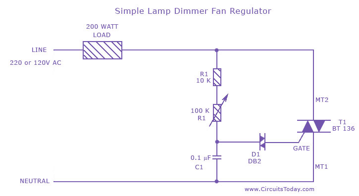
A fan regulator circuit that can also function as a simple lamp dimmer circuit. This fan speed regulator or light dimmer operates based on power control using a triac. The fan regulator circuit is designed to control the speed of...
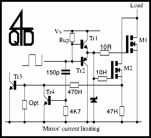
The circuit shows the method of mirror current sensing a MOSFET. A fully conducting MOSFET is resistive and behaves exactly as a resistor. It therefore you limit the voltage across the MOSFET when it is conducting you automatically limit...
This simple dimmer consists of only two components and can be easily integrated into a mains switch. It is essential to first switch off the associated branch circuit in the fuse box, as mains voltage poses a danger. The...
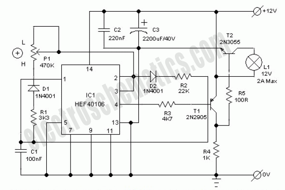
A user is new to the forum and has limited experience in DIY electronics. The current project involves creating a battery-powered LED dimmer circuit. The objective of the project is to design a battery-operated LED dimmer circuit that allows for...