
2500W Phase Control

This circuit is designed for controlling high-power resistive and inductive loads while ensuring safety and functionality through sophisticated components and configurations. The Siemens TLE3103 serves as the heart of the control mechanism, providing phase control capabilities essential for managing the load effectively. With its integrated power supply and zero voltage crossing detection, the TLE3103 minimizes electrical noise and enhances the reliability of the circuit.
The circuit’s operation is intuitively managed through a pair of pushbuttons, which adjust the output of the digital potentiometer, allowing for precise control over the load's power level. The debouncer IC (MAX6817) ensures that the pushbutton inputs are stable, eliminating the effects of mechanical bouncing that can lead to erratic behavior in digital circuits. The choice of the AD5228 digital potentiometer allows for a significant range of adjustment, with the potential for midscale or zero scale startup configurations depending on the jumper setting.
The use of the BTA41 triac, while rated for higher currents than necessary, provides an added layer of safety due to its isolated body, which is particularly advantageous when handling the circuit under load conditions. The snubber circuit, consisting of a 68 μH inductor, is critical for suppressing voltage spikes that can occur during the switching of inductive loads. The option to replace the inductor with a resistor offers flexibility in design, with the requirement to adjust the capacitor value accordingly to maintain circuit performance.
Overall, this circuit exemplifies a well-engineered solution for controlling high-power loads, integrating user-friendly controls and robust components to ensure both functionality and safety in operation.This circuit controls resistive and inductive loads up to 2, 500W. Its main functional device is an integrated phase control circuit - Siemens TLE3103. It contains its own power supply, a zero voltage crossing detector circuit and a logic driver. An additional feature is the low voltage input to enable/disable triac firing enabling/disabling the lo gic driver. The function is as follows: pin13 TLE3103 open (floating), trigger output active, tied to ground trigger output disabled. An UP and a DOWN pushbutton control a 32-step digital potentiometer (IC2, AD5228) via the debouncer IC1 (MAX6817).
The digital potentiometer has a power on reset pin which might be tied to ground causing the potentiometer to start at midscale, or to VCC causing it to start at zero scale. The desired function is selectable using jumper JP1. The triac (capable of driving 40A loads) is a bit overkill for the desired power but the BTA41 has an isolated body and therefore handling of the board under voltage is less dangerous as it is with phase on the package.
The snubber circuit uses a 68 H inductance but this might be replaced with a 100 resistor. When replacing the inductance C5 should have a value of 47nF. Remark: The debouncer circuit is manufactured with a SOT23-6 package. It might be soldered directly onto the board (DIP-6 package) using thin wires or an adapter board. 🔗 External reference
Related Circuits
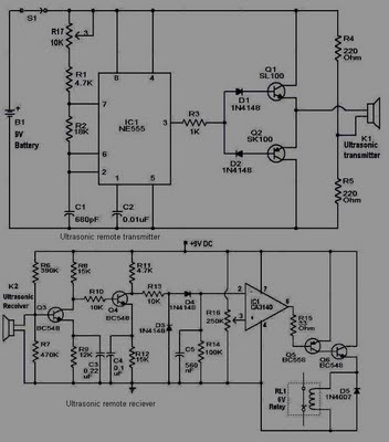
This circuit is straightforward and well-defined. The transmitter operates at 9 volts, while the receiver circuit functions at 5 volts. The transmitter utilizes a 555 timer and two SL100 transistors to perform its function. The receiver incorporates a small...
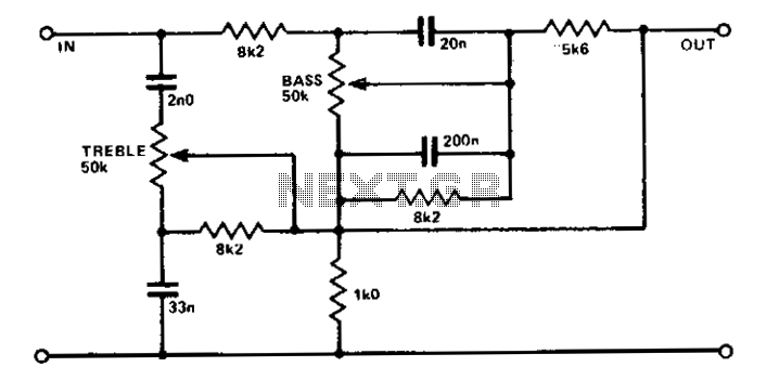
A simple circuit using two potentiometers and easily available standard value components provides tone control. The impedance level is suitable for low-level transistor or op-amp circuitry. This tone control circuit typically employs two potentiometers to adjust the bass and treble...
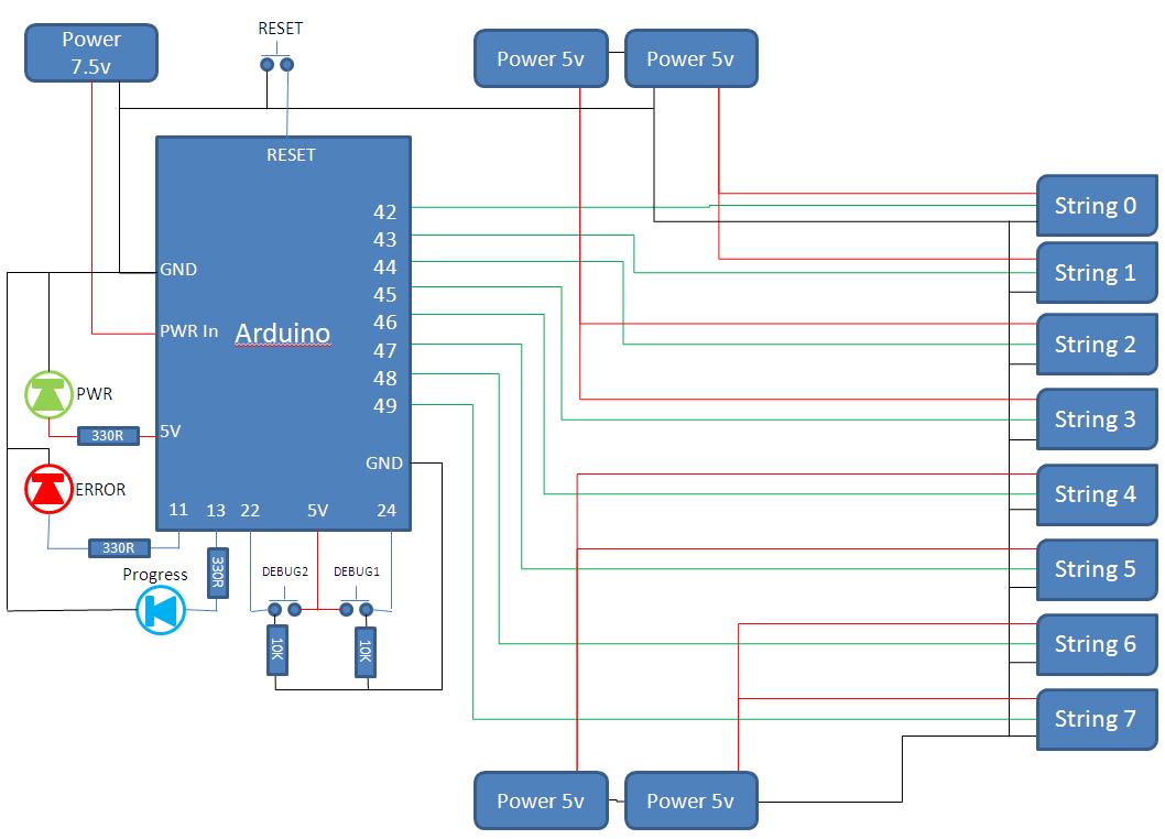
This project develops a Christmas lights controller for GE Color Effects lights, enabling programmed control of up to eight sets of lights. It includes a function-specific language for programming light patterns and an emulation environment for testing programs before...
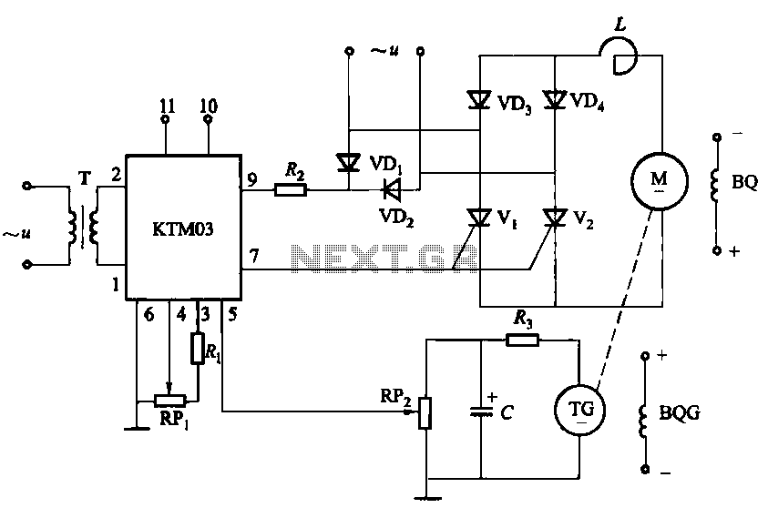
The adjustment potentiometer for the Raspberry Pi can modify the conduction angle of the thyristor VI and V2, which in turn adjusts the speed of the DC motor M. The speed feedback circuit is implemented using a tachometer generator...
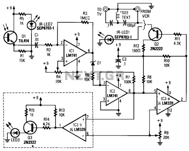
A signal from an infrared (IR) remote control is converted from IR radiation to a frequency pulse that can be transmitted through coaxial TV cable or any other two-conductor wire to another room, where it is converted back into...
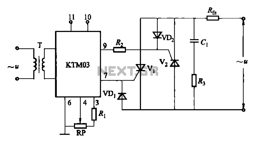
Adjustment potentiometer RP can modify the conduction angle of thyristor Vl, vz, thus altering the voltage applied across the load Rfz. The adjustment potentiometer (RP) serves a critical role in controlling the conduction angle of the thyristors Vl and vz within...