
2500W Phase Control Circuit Schematic

The 2500W Phase Control Circuit is designed to regulate the power delivered to a load by controlling the phase angle of the AC waveform. This type of circuit is commonly used in applications such as dimmers for lighting, motor speed controllers, and temperature control in resistive heating elements.
The schematic typically includes several key components: a triac or thyristor for switching, a zero-crossing detector to synchronize the control signal with the AC waveform, and a control circuit that determines the phase angle at which the triac is triggered.
The ground-tied trigger output ensures that the circuit remains stable and prevents false triggering due to noise or fluctuations in the input signal. The low voltage input feature allows the circuit to be controlled by low-power microcontrollers or other low-voltage control devices, enhancing its versatility in various applications.
In practical implementations, it is important to include appropriate snubber circuits across the triac to protect it from voltage transients and to ensure reliable operation. Additionally, heat sinks may be necessary to dissipate heat generated by the triac under high load conditions. Proper design considerations for component ratings, layout, and thermal management are crucial to ensure the reliability and efficiency of the phase control circuit.
This circuit can be utilized in various applications where precise control over power delivery is required, making it a valuable tool in modern electronic design.The following circuit shows about 2500W Phase Control Circuit Schematic. Features: tied to ground trigger output disabled, ow voltage input to .. 🔗 External reference
Related Circuits
This schematic illustrates a simple yet effective LED dimmer circuit utilizing the well-known voltage regulator IC LM317T. The LM317T can function as a current regulator, as demonstrated in this circuit. It features ten super bright white LEDs, although the...
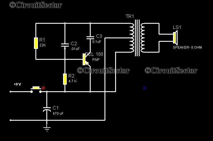
This circuit is a low-cost, one-touch doorbell using a Bel 188 transistor. It is likely one of the most economical bell circuits that can be constructed. The core component of this circuit is the output transformer from a push-pull...

A continuously operating wiper in a vehicle can be bothersome, particularly during light rain. The circuit outlined here allows for the adjustment of the wiper's sweeping rate, ranging from once per second to once every ten seconds. The circuit...
Control a small DC motor using an H-bridge with an Arduino Uno. The objective is to enable the motor to rotate in different directions based on left and right key presses on a keyboard. The provided code includes the...

This 49-MHz FM transmitter comprises an audio amplifier, a low-pass filter, three RF stages, and a regulated DC power supply. The output power is approximately 16 mW into a 50-ohm load. This transmitter is suitable for various 49-MHz applications,...
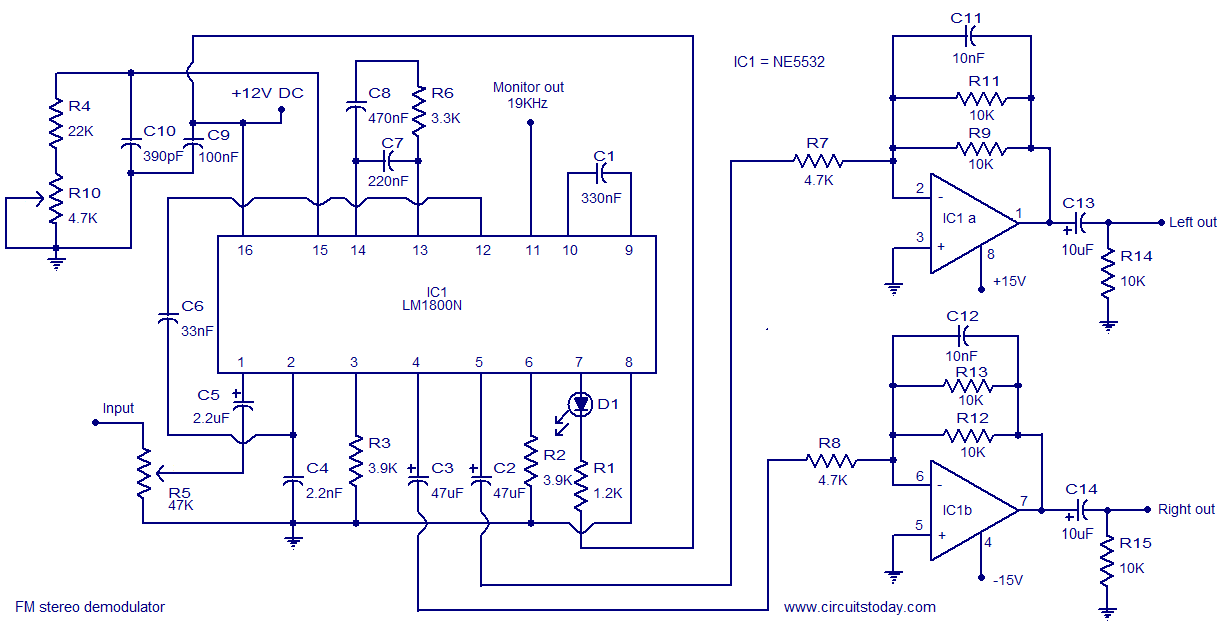
The following circuit illustrates the LM1800 IC Integrated FM Stereo Demodulator Circuit. Features include excellent sound quality and high-quality FM stereo. The LM1800 Integrated Circuit (IC) serves as a highly effective FM stereo demodulator, designed to deliver superior audio performance...